Study Method / Setup:
We will examine the behavior of a single cell in the 1005B and, in fact, only one side wall of a single cell. The assumption is that all cells and all cell walls are identical.
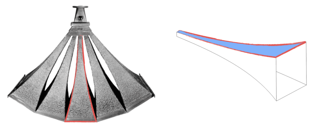
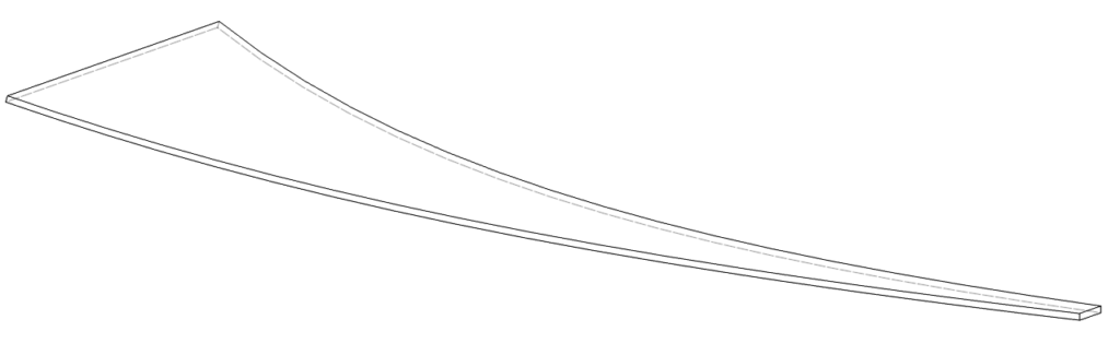
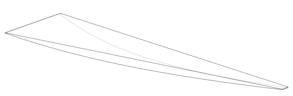
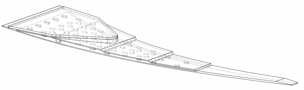
The image below shows a typical “wedge” for this study. Three ends are fixed as shown. A static deflection simulation will be performed by applying pressure onto the entire interior wall. A modal simulation will be performed with the same constraints minus pressure.
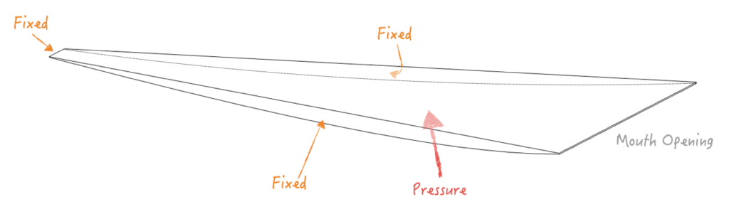
Note: This assumes the Mouth Opening is unconstrained by adjacent cells and should represent the worst case free deflection.
Assumptions:
The following properties are assumed for the simulation. Only elastic properties will be used to due low deflection.
| Material | Properties |
|---|---|
| 1005B Cell | Material: Steel Elastic Modulus: 210GPa Density: 8000 kg/m³ |
| 3D Printed Cell | Material: PETG HF Elastic Modulus: 2GPa (100% infill) Density: 1400 kg/m³ |
| Aluminum Stiffener | Material: AL6061 Elastic Modulus: 70GPa Density: 2700 kg/m³ |
| Steel Stiffener | Material: Steel Elastic Modulus: 210GPa Density: 8000 kg/m³ |
The original 1005B is assumed to have cell wall thickness of 20ga (~1.0mm). This is the best guess I could find online.
For configurations with stiffeners, the bond is assumed to be ideal line-to-line contact with no glue thickness.
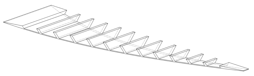
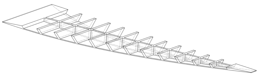
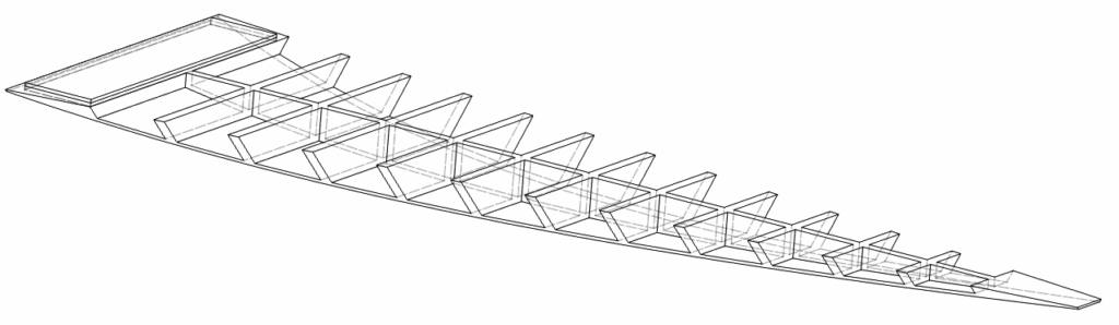
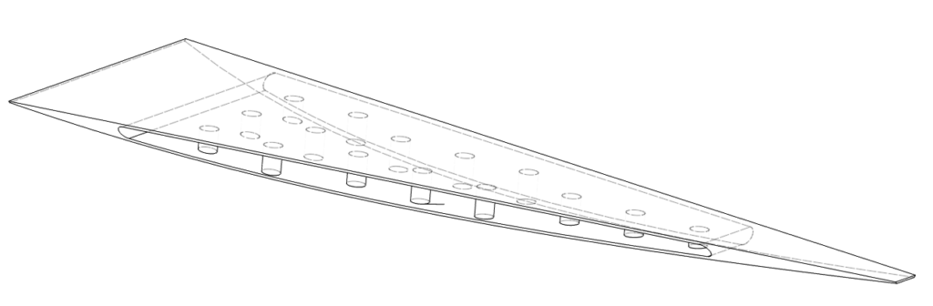
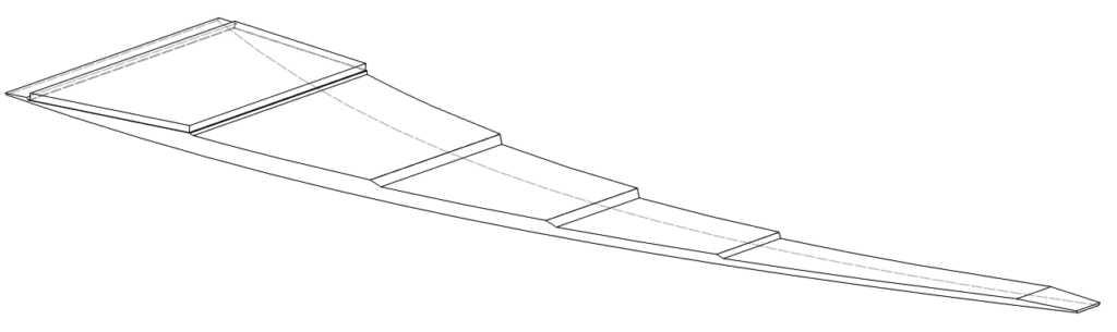
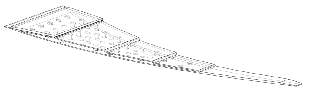
Design Configurations:
Many brainstorming concepts are shown below, ranging from the simplest case to rather elaborate designs. Hollow internal features and various stiffener configurations were explored.
Steel – Baseline
20ga (1mm) Steel
Steel – Thin
26ga (0.5mm) Steel
PETG – Solid
3mm
PETG – Ribs #1
PETG – Ribs #2
PETG – Ribs #2 + Stiffener
PETG – Wedge
PETG – Wedge Hollow
PETG – Stepped + Stiffener
PETG – Stepped Hollow +
Stiffener
PETG – Stepped Hollow +
Stiffener 2
Static Deflection Results:
ANSYS was used to evaluate the design. The mesh was generated using the automatic tool (manual refinement was not done.) As visible below, the software defaulted to a mix of quad and triangular meshes.
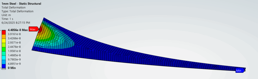
Pressure of 1Pa was applied to the internal surface (equivalent to 93dB SPL). This should represent a home listening level. As reference, the Altec 288-16K compression driver is capable of producing 110dB SPL @ 1W (or 6Pa @ 1W) and has a maximum input limit of 15W!
The resultant deflection from the 1Pa pressure is minuscule and well within the linear region. As an example, the Steel – Baseline config shows a maximum deflection of 4.4×10⁻⁸m or 44 nanometer. We can expect the displacement to increase for higher operational pressure but it should still be within the linear region.
Steel – Baseline
20ga (1mm) Steel
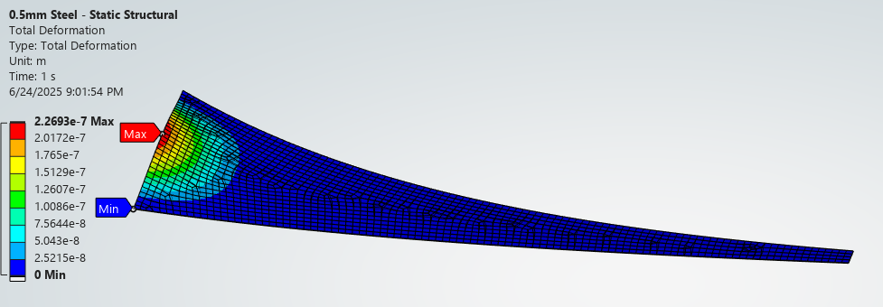
Steel – Thin
26ga (0.5mm) Steel
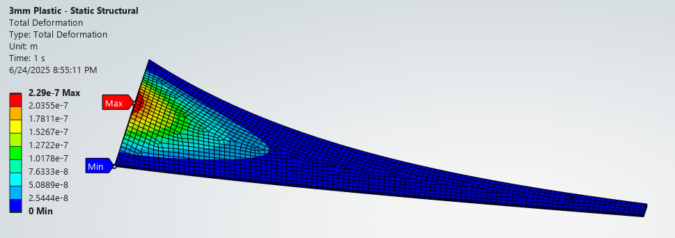
PETG – Solid
3mm
PETG – Ribs #1
PETG – Ribs #2
PETG – Ribs #2 + Stiffener
PETG – Wedge
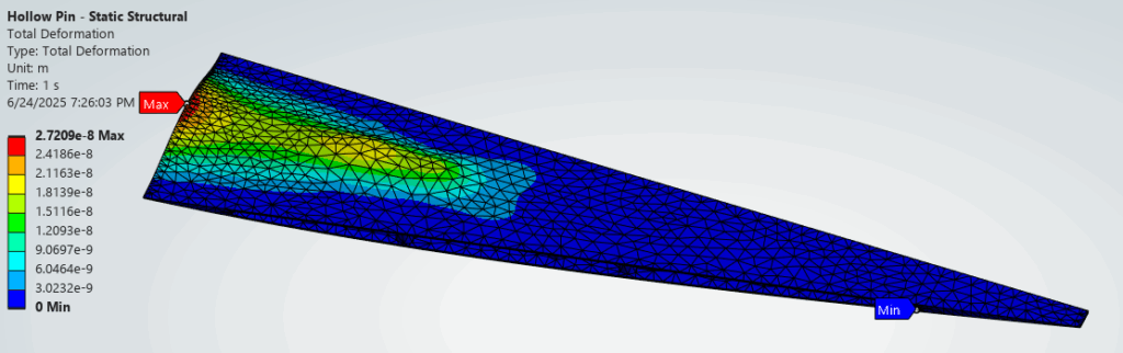
PETG – Wedge Hollow
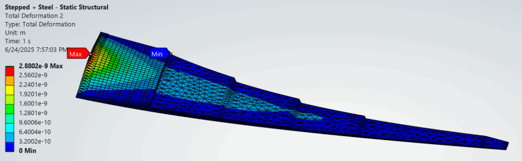
PETG – Stepped + Stiffener
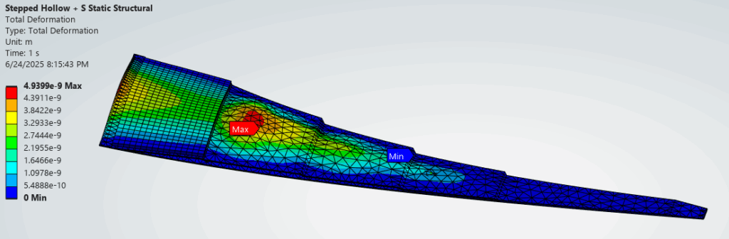
PETG – Stepped Hollow +
Stiffener
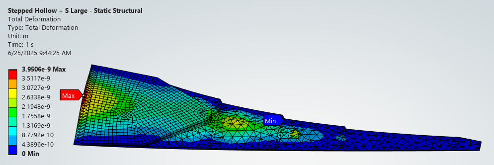
PETG – Stepped Hollow +
Stiffener 2
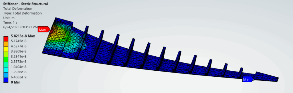
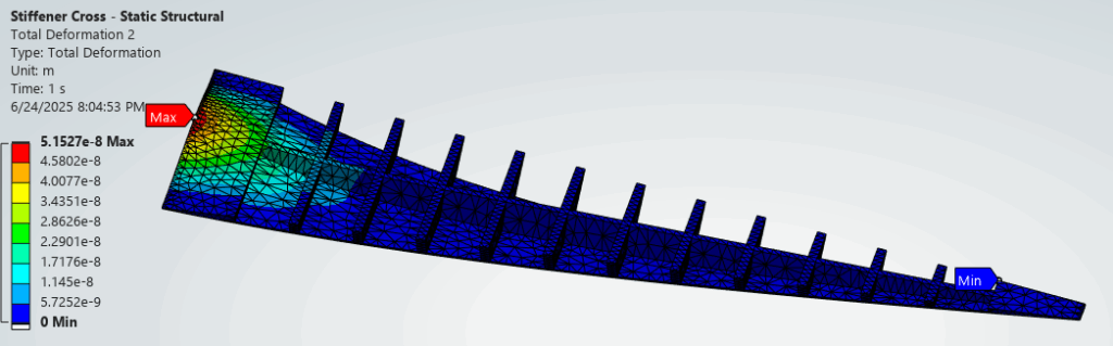
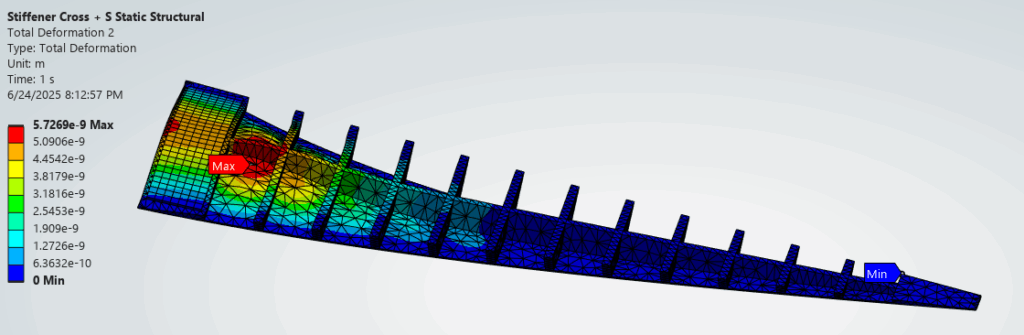
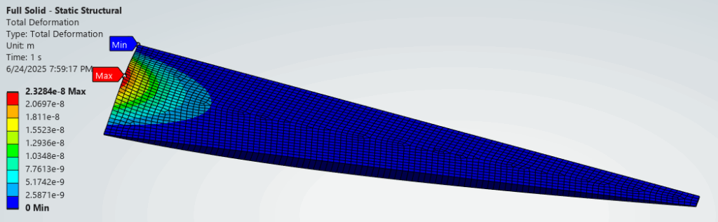
The weakest point is at the mouth opening for most configs. This is expected due to the large span. PETG configs are much weaker than Steel but adding cross section helps greatly. PETG configs with metal stiffeners are able to further reduce maximum deflection by an order of magnitude.
Modal Simulation Results:
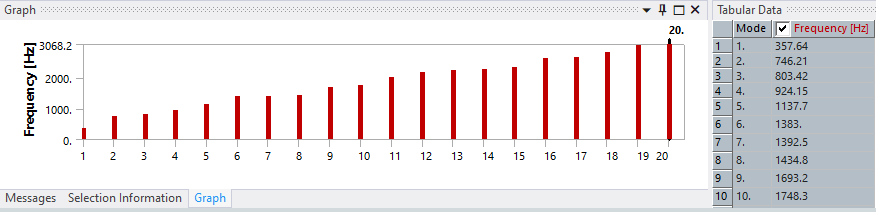
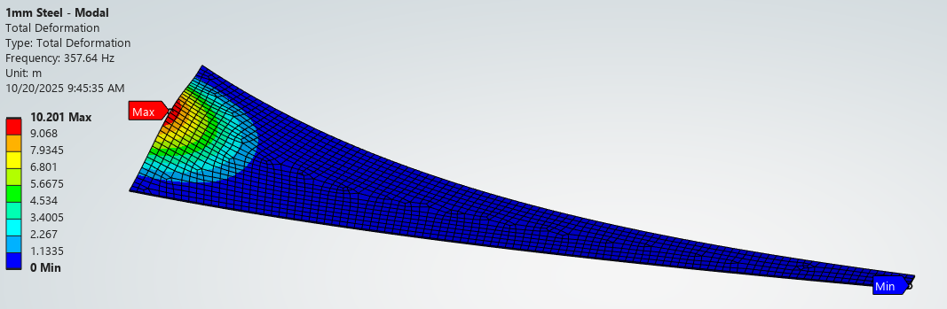
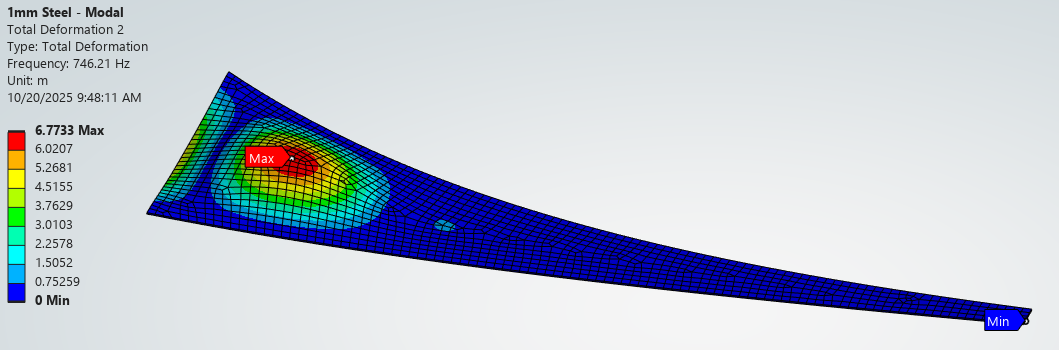
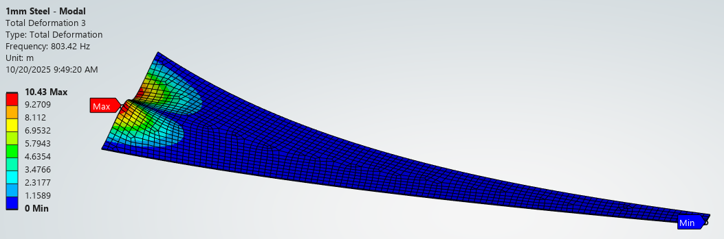
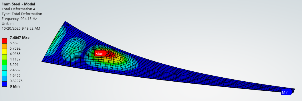
The modal simulation output and first four deflected shapes for the Steel – Baseline config is shown below. The first mode, lowest frequency, is located at the mouth and higher modes involve material farther away.
Interestingly, the third mode is transverse across the mouth. I’m curious if this mode can actually be excited by an acoustic pressure wave since the air displacement volume cancels out. Many such transverse modes exist in the simulation.
Conclusion:
In summary, eleven different configurations were tested for both static and modal behavior. The configs started as constant wall thickness cases to establish baseline and iterated into more elaborate designs. Majority of the effort was made to minimized static deflection in the mouth region.
Note: many material assumptions and mesh simplifications were made to simplify the simulation. The results should only be used for comparative study and have not been correlated to physical behavior.
| Configuration | Max Deflection (10-8m) | 1st Mode | 2nd Mode | 3rd Mode | 4th Mode |
|---|---|---|---|---|---|
| Steel – Baseline (1mm) | 4.47 | 357 | 746 | 803 | 924 |
| Steel – Thin (0.5mm) | 22.7 | 219 | 463 | 509 | 619 |
| PETG – Solid (3mm) | 22.9 | 259 | 496 | 636 | 718 |
| PETG – Ribs #1 | 5.82 | 458 | 1006 | 1097 | 1263 |
| PETG – Ribs #2 | 5.15 | 501 | 1105 | 1167 | 1697 |
| PETG – Ribs #2 + Stiffener | 0.57 | 614 | 1355 | 1523 | 1790 |
| PETG – Wedge Solid | 2.33 | 747 | 1334 | 1621 | 1964 |
| PETG – Wedge Hollow | 2.72 | 597 | 701 | 947 | 1100 |
| PETG – Stepped + Stiffener | 0.29 | 1000 | 1871 | 2087 | 2473 |
| PETG – Stepped Hollow + Stiffener | 0.49 | 696 | 1216 | 1448 | 1627 |
| PETG – Stepped Hollow + Stiffener 2 | 0.39 | 767 | 941 | 1594 | 1762 |
We are able to infer the following static deflection behavior:
- For PETG only configs: adding material at the mouth is able reduce max deflection. Some configs are able to match max. deflection of the baseline.
- For PETG + stiffener configs: max. deflection can be further decreased 10x of the baseline. Is this actually beneficial for acoustic performance though?
- Deflection Zone: max. deflections typically occur at the mouth where the span is largest.
We are able to infer the following modal behavior:
- For thin wall and PETG only configs: low resonant frequencies are observed. Many have the 1st Mode below the 500Hz intended cutoff. Maybe this means they won’t be excited? But for many, the following three modes fall between 500 – 1000Hz and can definitely be excited. It will be important to find damping material that can be effective at these frequencies.
- For thick wall and stiffener configs: First resonance is pushed much higher to the 500-1000Hz region and following modes are way above 1000Hz. This is beneficial as higher frequencies as easier to absorb with thinner damping material.
- Modal Zone: All first four modes occur near the mouth.
Next Steps:
The above result confirms my initial suspicion that the mouth section can indeed be problematic from a rigidity and resonance perspective. There are several configs that look hopefully (especially the stiffener configs.) It is optimistic to see that adding local cross section in PETG is able to match the mouth stiffness of the baseline.
The next step is to start building some of these configs.
Leave a Reply