Original Manufacturing Method:
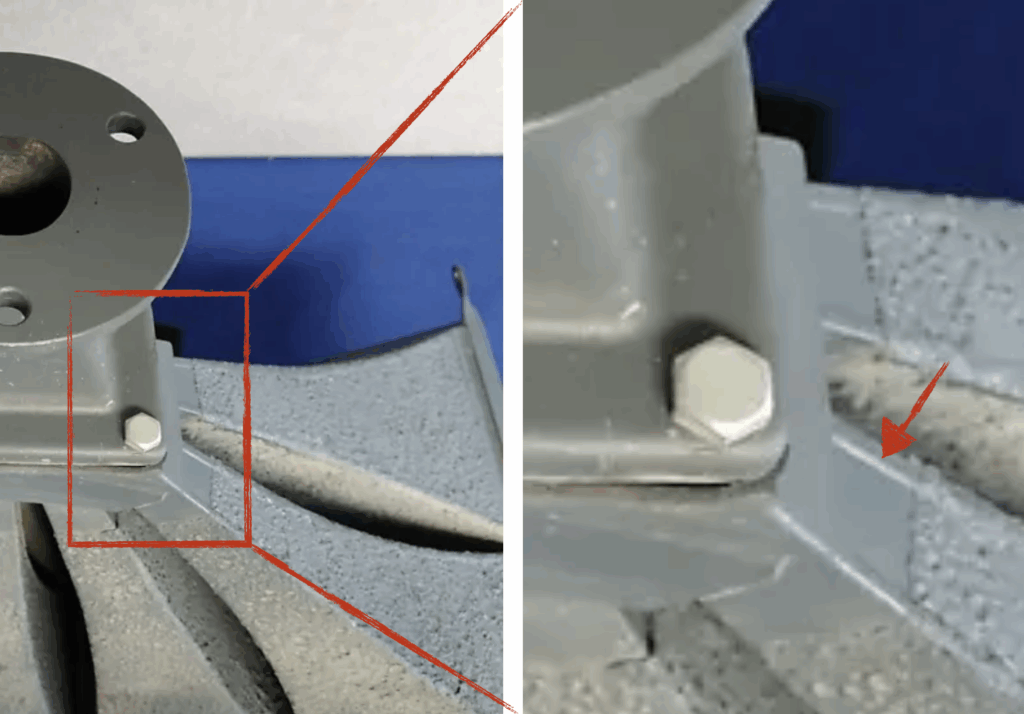
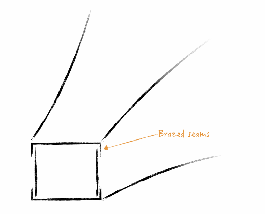
The original multicellular horns were manufactured using sheet metal brazing. Individual cells were first assembled consisting of the four sides. Two of the sides have stamped flanges to allow the braze to fill. This is visible in the images below. The four sides were then placed into a fixture and carefully hand brazed by skilled technicians.
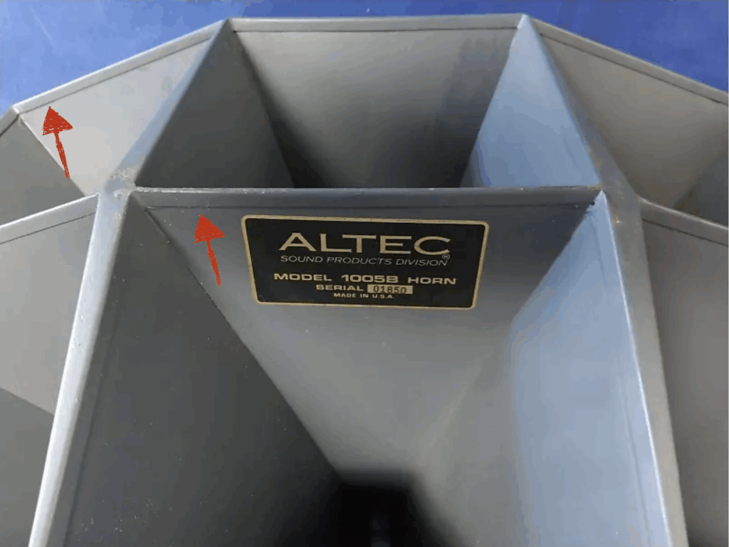
Damping material was then applied over the majority of the cell. The ten cells (ie: for building a 1005B) were then fixtured into the correct position and brazed into the final assembly. I assume there is leeway to “massage” the length and shape of each cell to nicely fit each other. A sheet metal cap is then added to the mouth region which stiffens the edges, fills the in-between gaps, and provides a nice cosmetic finish.
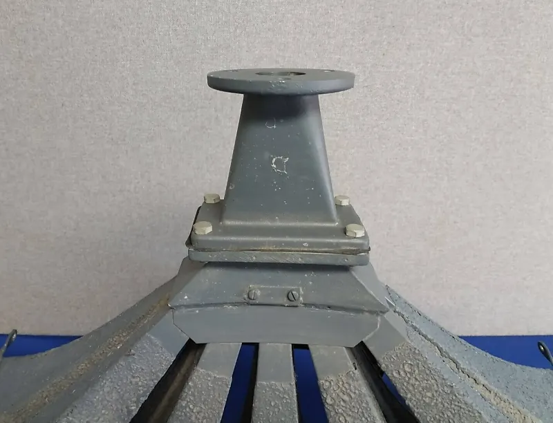
On the throat end, cell-to-cell regions were brazed to seal the gaps. A cap (appearing to be brass casting) is then brazed around the terminate to allow attachment of the throat adapter. The multicellular is now essentially complete. This is all very labor intensive work! It requires many tools to correctly manufacture and assemble the components. To achieve this quality is quite incredible and I wonder if it is still a feasible product today.
Subcomponent Division:
While it is possible to completely replicate the original method, it is the 21st century, and we now have access to more tools than ever. The goal of this project, as previously stated, is to explore 3D printing as the primary manufacturing process. It will allow prototyping and manufacturing of near-net-shape components requiring minimal labor.
The first step is to decide how to split the 1005B into smaller chunks for manufacturing. The entire horn is much too big to fit onto a standard 3D printer. In this case, the size limit is a Bambu Lab X1C with a moderate print volume of 256 x 256 x 256 mm (~10.25 x 10.25 x 10.25 in).
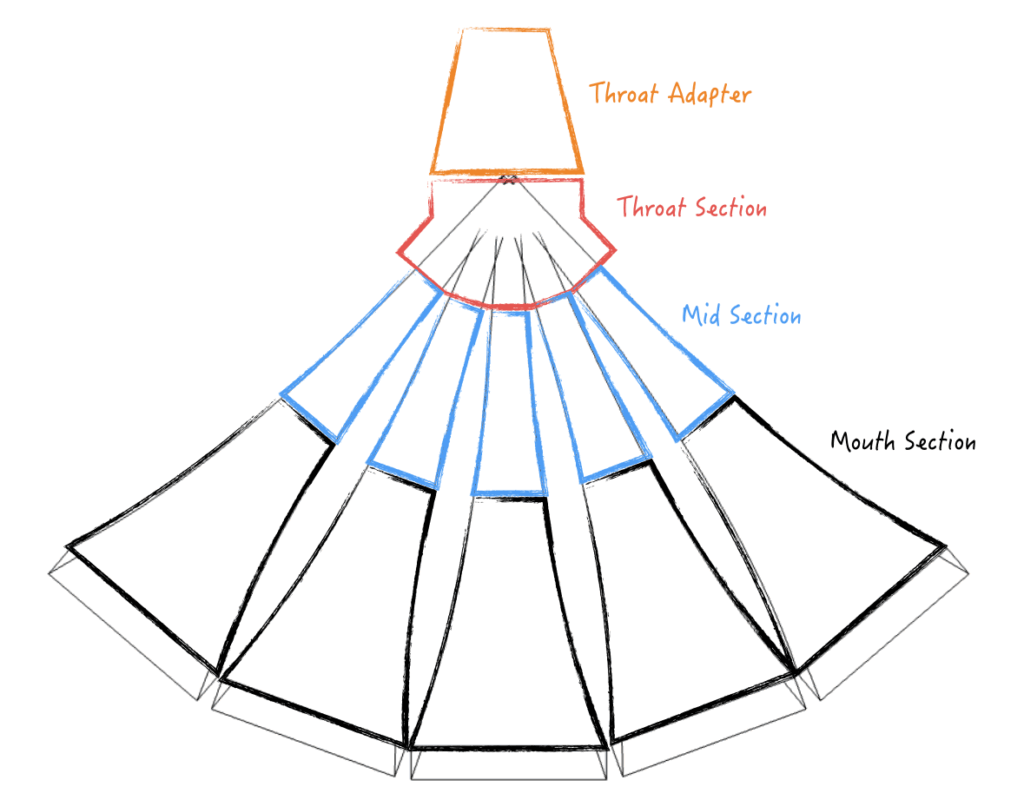
I decided to attempt splitting each cell into three pieces (mouth, mid, and throat section). The mouth and mid section should ideally be the same for all ten locations.
The throat section should ideally be combined to capture the detailed geometry and thin walls where sound is split. The region is of particular interest because it handles the transition from plane wave to “spherical” wave. It will be interesting to optimize this transition and be able to do so without rebuilding the whole prototype.
The throat adapter is for expanding the CD (compression driver) exit to the correct rectangular shape. Building this as a separate piece will allow experimenting with different expansion rates and also CD’s with different exit diameters.
Assembly Method:
The horn should be easy to assemble using reversible fasteners. The preference is to use machine screws with threaded inserts. This will allow the horn to be dis-assembled without accumulating wear on the plastic.
Each section needs to have a tight fit to ensure acoustic performance. Gaskets will be used at joints to ensure seal.
Design Overview:

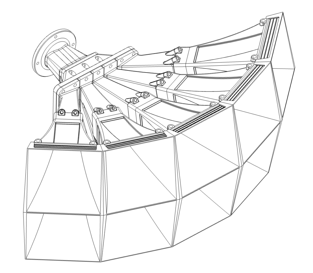
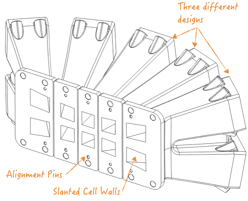
Below is the final iteration of the first-prototype design with all the details ironed out. The design mostly follows the intent set out above. Symmetry is used where possible. All sections are 3D printable without needing support material. The mouth sections are identical for ease of manufacturing.The mid sections are not identical because of a planar joint to the throat section. This requires three different designs to match the angles. This planar face is the downward face for 3D printing and provides adhesion for the overhang. Screw bosses/threaded inserts are used as fastening between sections. We will explore the design in more detail below.
Mouth Section:
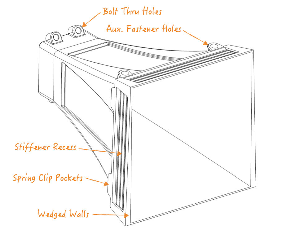
The mouth section is the largest section of this design and takes almost the entire Z-limit of the 3D printer. It is meant to be printed mouth-opening down for stability and no support material is required for any overhangs.
The mouth walls are wider at the bottom to take up gaps to adjacent cells. The geometry shown is specifically for the 1005B stacking pattern. The wedge will be much larger for the 1505B. The internal walls maintain the original square profile.
Wall Thickness: Different thicknesses/infills are being considered with respect to acoustic performance vs. manufacturability. The cell wall near the mouth is exceptionally thin/long and therefore not rigid. Material has been added here to enlarge to contact area between cells to provide rigidity. Metal stiffener pockets are also added so aluminum/steel plates can be glued if needed. This is especially important for the outer edges of each cell (where there is no adjacent support).
The plan is to experiment with different combinations of wall thickness/damping material/stiffener to achieve the best performance. Thicker walls will be stiffer but can increase print time (high infill). Stiffener and damping material can be added but can increase assembly labor.
Mid Section:
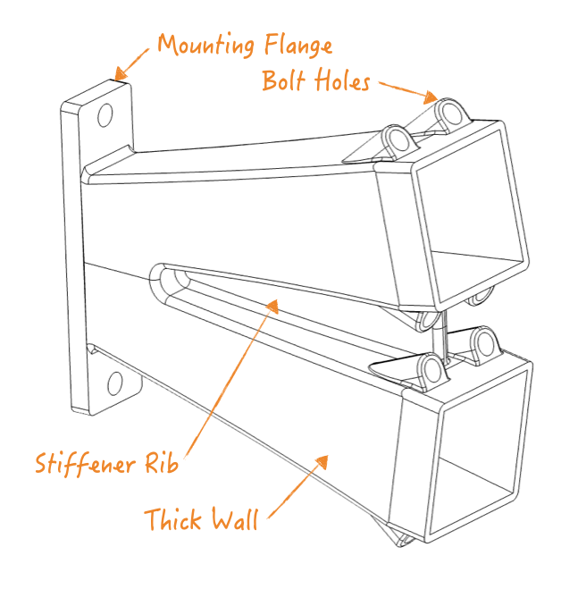
The mid section will perhaps be the most difficult section to print due to the significant overhang. The upper/lower cells of each 1005B “cell column” have been joined due to limited spacing and will improve component strength. Threaded inserts are to be heat-staked at the mouth joint side. The spacing here is quite tight and will need to be checked during assembly. The walls are purposefully designed very thick for acoustics and strength. Print time is significantly impacted due to smaller component size.
Throat Section Interface: The decision to use a planar joint for this interface is a risk. The alignment and tolerances must be controlled carefully to prevent acoustic discontinuity at this junction. Ideally, the horn profile should be entirely continuous without any disruption that can cause reflections. The sealing gasket here represent a challenge as well and needs to follow the tapered geometry of the opening. Dowel pins have been added for alignment but success will ultimately depend on the print quality.
Throat Section:
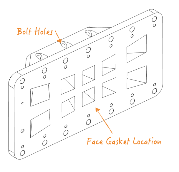
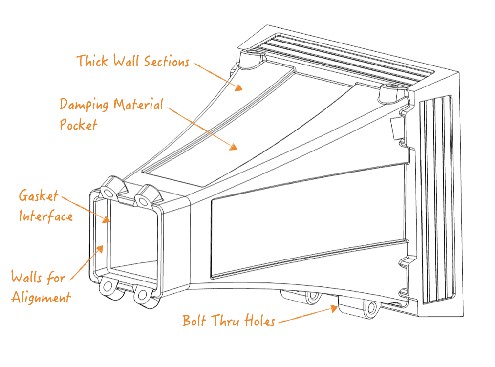
The throat section faces the same manufacturing challenges as the mid section above. The component is to be printed “Face Gasket” face down and has significant overhang right from the start. First layer adhesion and cooling parameters will be critical to get the geometry right and prevent elephant-foot/other defects. This component is very rigid as it needs to reliability connect the horn section to the heavy compression driver.
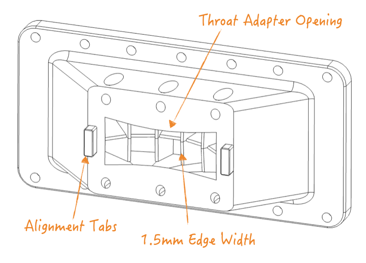
Acoustic Splitting Geometry: The current splitting design into the ten cells is questionable. The exponential expansion is continued as far as possible but eventual overlap and turns into undefined expansion. The interface opening is also not rectangular but a hourglass shape. The splitting “wedges” are minimized to ~1.5mm thick with a round. This seems like a good starting point given the modulus of the plastic. Going thinner may just result in a thin resonant wall that colors the sound. These design details can be experimented with later but is sufficient for initial testing. This component can be easily iterated on without impacting its neighbors.
Throat Adapter:
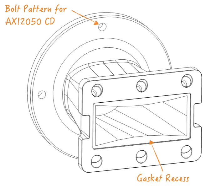
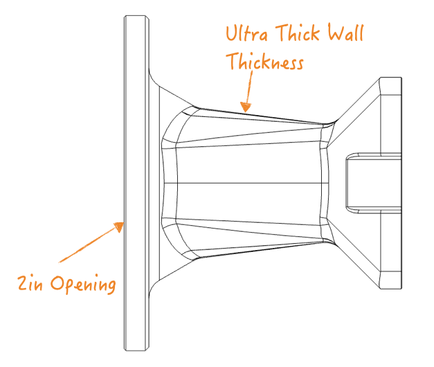
The throat adapter is a temporary design for now. The original Atlas design uses a 1.4″ exit compression driver (ie: Atlas 288) which transitions to a rectangular shape with an unknown expansion rate.
I am using a 2″ exit compression driver for now. The surface area of the hour glass shape is almost the same the 2″ exit. Therefore, this throat adapter is provides only shape change but no expansion. The effect of this is to be seen and may result in weird resonances. This component will be iterated on as well for different compression drivers.
Wall Thickness / Damping / Acoustic Performance:
At this point, the biggest question is the acoustic performance of the 3D printed parts. There is an almost infinite combinations of wall thickness / infill / damping / stiffener to experiment with. Intuitive, the mouth section appears to be the most challenging as it interacts with the lowest frequencies and has the thinnest walls with largest span. Wall resonance here seems likely.
The other sections are physically smaller, don’t have such space constraints, and can be easily made stiffer. They are, however, subject to higher pressure from the compression driver. This may become an issue at high levels but shouldn’t be for home use (maybe I need to clarify my design requirement). I’m also curious if the lower elastic modulus of plastic will regardlessly color the sound (compared to a metal surface).
Next Steps:
It is perhaps worth evaluating a smaller section of the horn instead of building the entire 1005B at once. The mouth section will be investigated first for wall resonances and design alternatives. It will be a good read on feasibility of 3D printed horns.
Leave a Reply