Category: Altec 1005B – Multicellular Horn Replica

  • Altec 1005B: #5 Mouth Section – Modal Simulation

    Initial Prototype:

    From the previous post (here), we discovered potentially problematic resonances at the Mouth Section (due to the low wall stiffness and large span.) We identified, through simulation, the first three vibration modes to be quite low and will probably require treatment.

    Several methods of treatment were discussed:
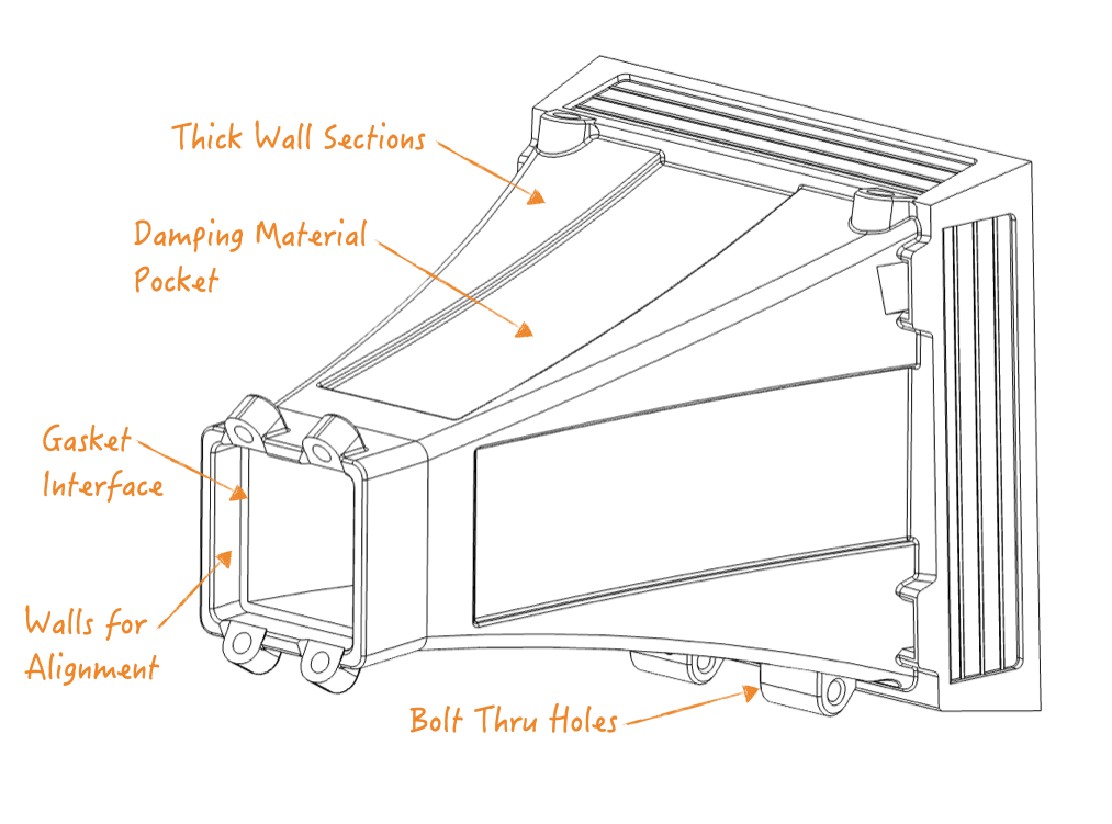
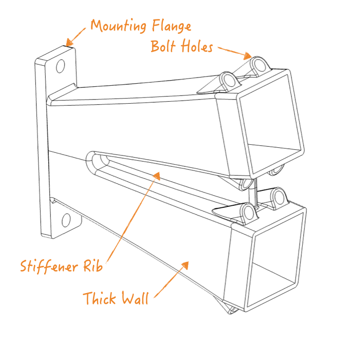
    1. Thicker Walls: increases wall stiffness
    2. Damping Material: absorbs vibrational energy
    3. Metal Stiffener: increases wall stiffness (where thicker walls are not possible)

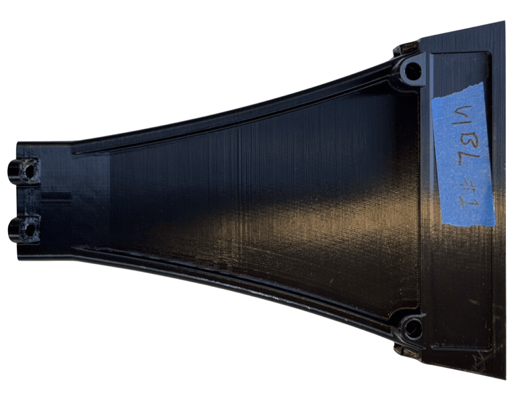
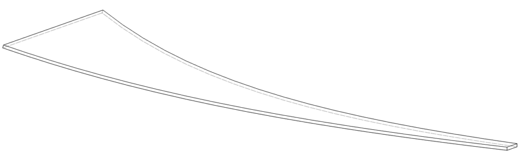
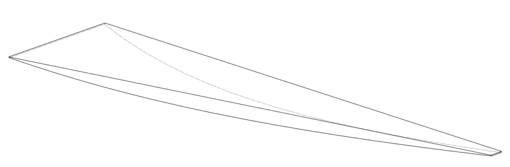
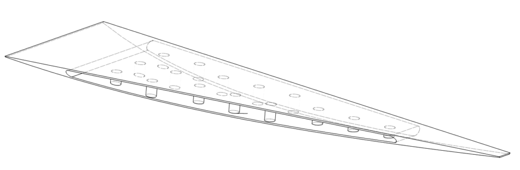
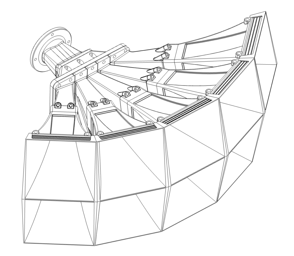
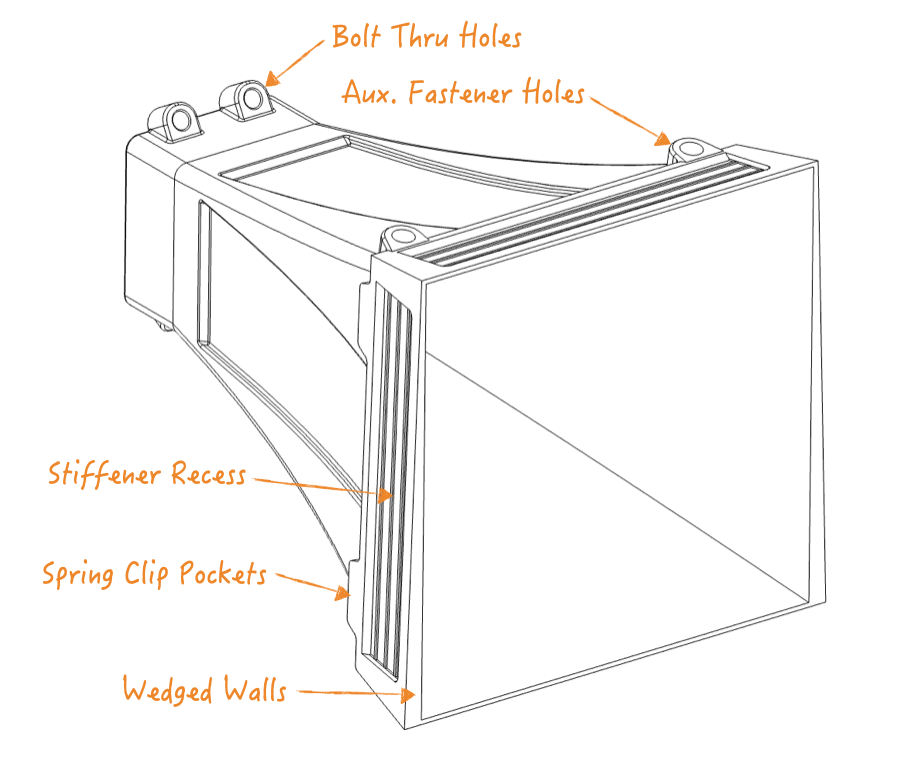
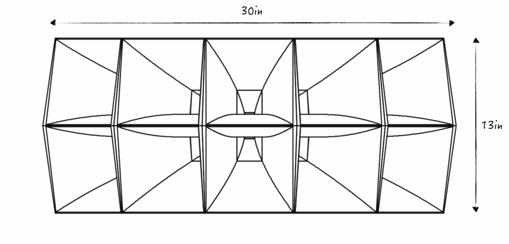
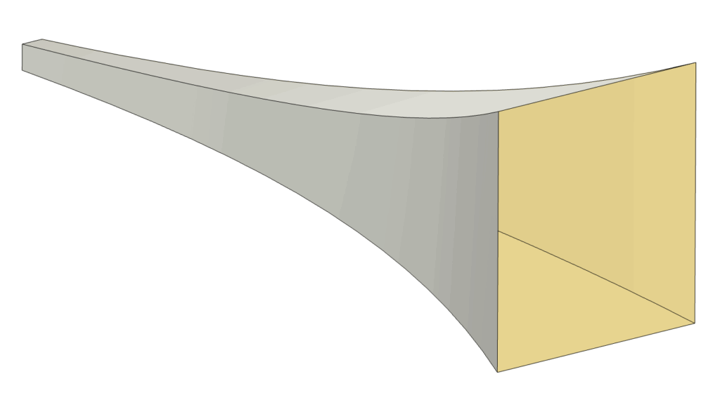
    An initial prototype, with the simplest geometry, was designed and printed. This is the baseline design and had thin walls, no damping, and no metal stiffener.


    Test Fixture:

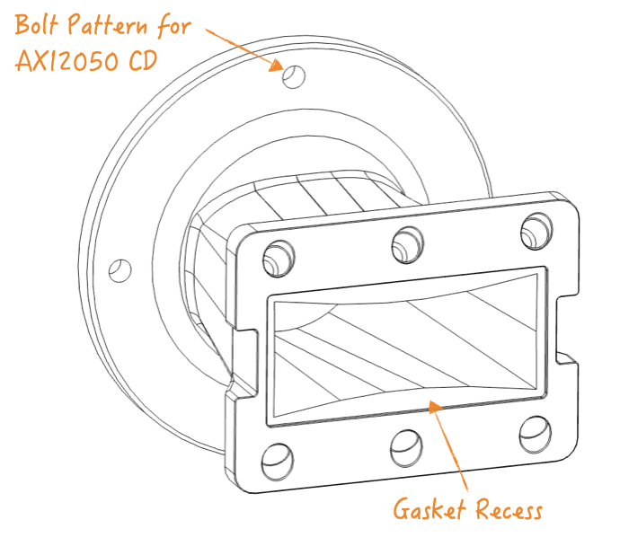
    A test fixture was designed and built to facilitate testing. The compression driver for this test is the wide band AXI2050 (capable of reaching 500Hz).

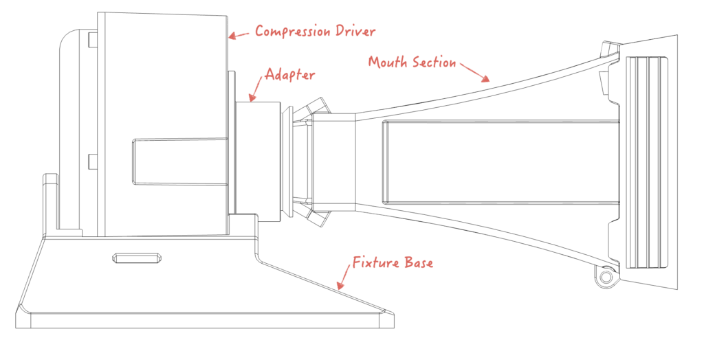
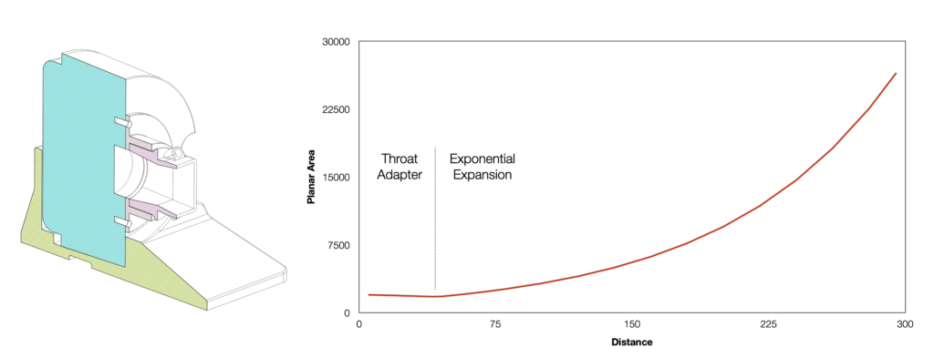
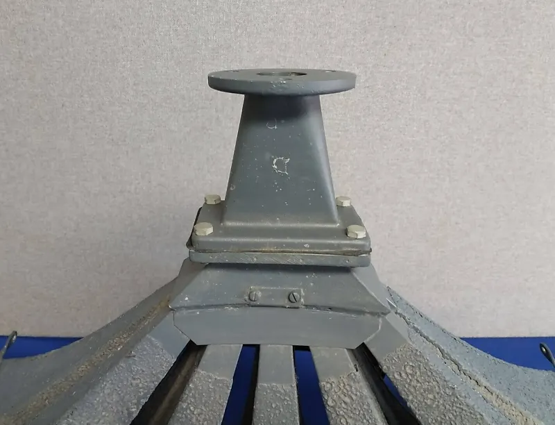
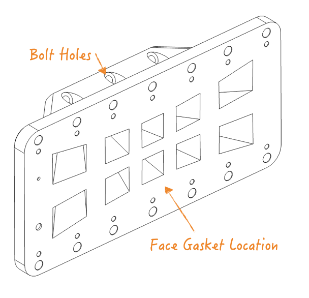
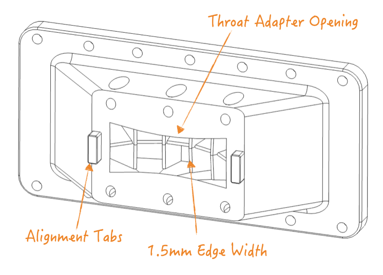
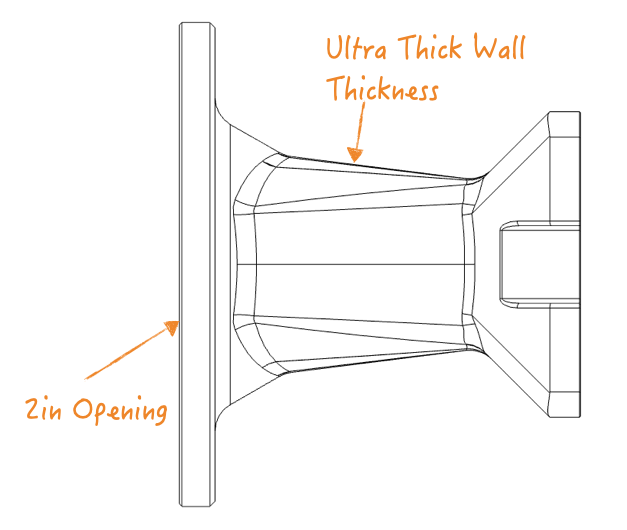
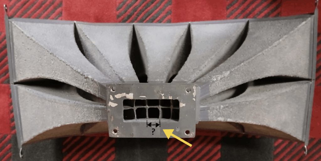
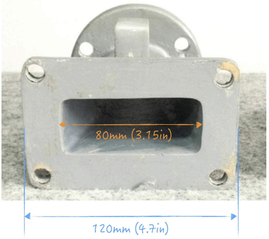
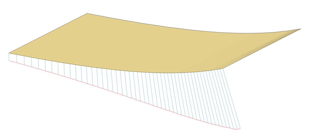
    An adapter transitions the CD exit to the rectangular geometry of the Mouth Section. The planar expansion area is shown below. Unfortunately, the throat adapter could not continue the exponential geometry of the Mouth Section. A slight linear reduction was needed to match.
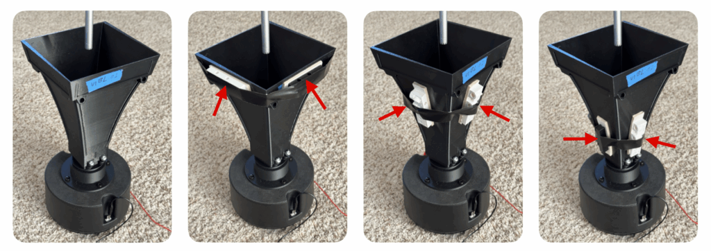

    Damping Experiment:

    Felt damping material was taped onto the mouth, near the mouth, and near the throat. Sweeps were taken to gather initial data.

    Test Setup:

    The horn was placed vertically with the compression driver resting on the floor. Fixture Base was not used. Microphone was placed directly in front and centered on the mouth.

    Care was taken to swap out each configuration without moving the compression driver or microphone. Capture settings and gains were kept identical for all measurements.

    Frequency: 300 – 15000Hz (no smoothing)
    Gating: 300ms

    Raw Measurements:

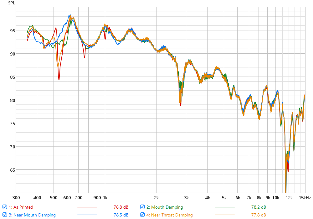
    In the FRQ (frequency response), we can see response variations mostly below 1500Hz. There are several resonance dips especially for the “As Printed” config. Above 1500Hz, response variation between configs is relatively small at 4000, 5100, and 11500Hz.

    All configs show a big dip at 2700Hz for all configs and this appears to be from mouth diffraction.

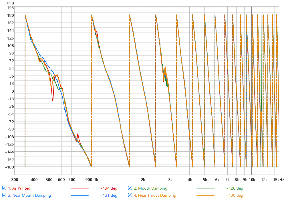
    The phase graph is useful for picking out resonances, appearing as dips / spikes surrounding the problem frequency. The pattern is similar to the above FRQ.

    Measurements (300-1500Hz):

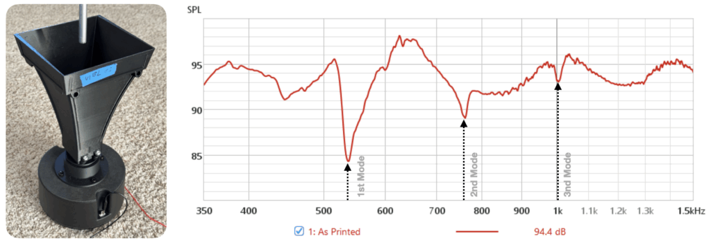
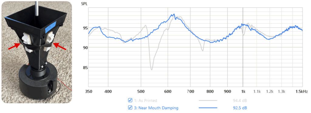
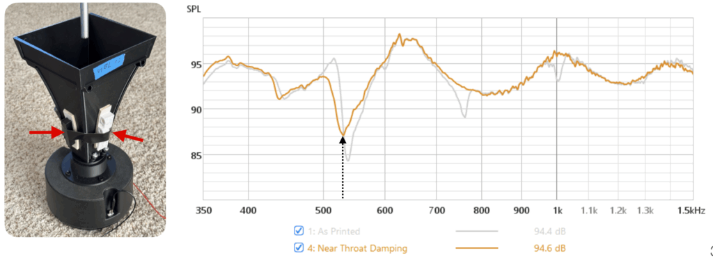
    Below, the results have been truncated down to 1500Hz to reveal more details. Configs are individually plotted with the baseline as reference. Three resonance dips are clearly visible and with various degree of improved based on damping.

    Baseline: Three dips observed at 540, 760, and 1000Hz which seem to correspond to the modal simulation.

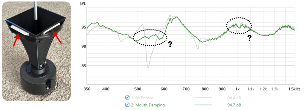
    Mouth Damping: Adding felt around the mouth reduced all three dips. But there is still something going on around 540 and 1000Hz.

    Near Mouth Damping: Moving the felt down smoothed all three dips even better.

    Near Throat Damping: 540Hz dip is back while the other two are gone. This aligns well with the modal simulation as the mouth opening is allowed to resonate again.


    Modal Simulation / Correlation:

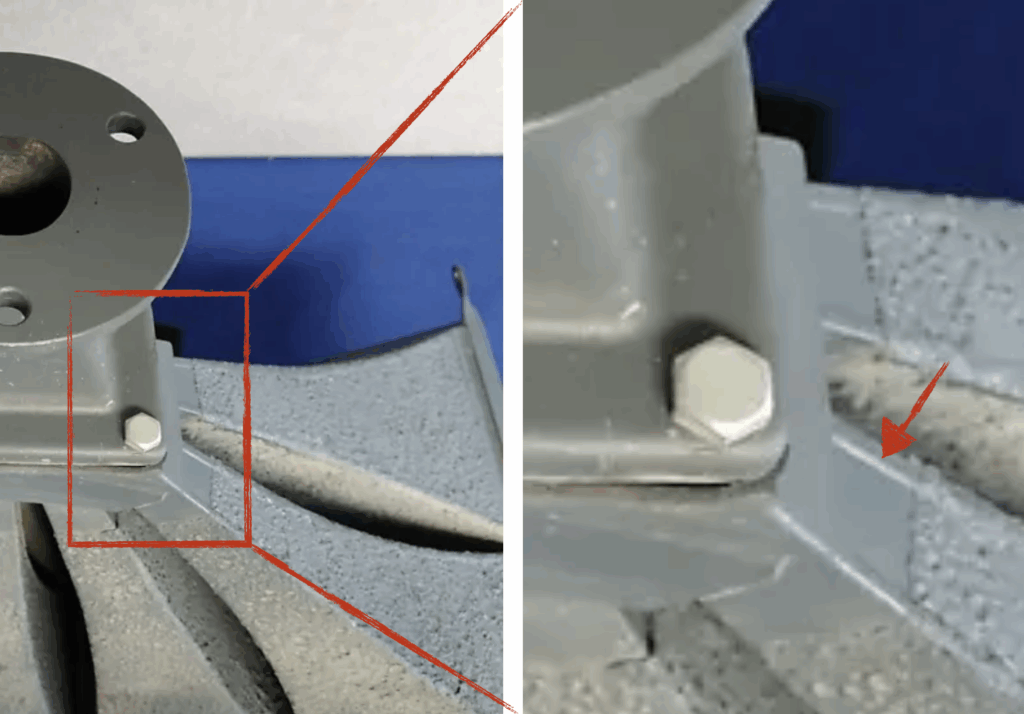
    The three resonances above (540, 760, and 1000Hz) don’t really line up with any of the simulation results on the previous page. This is to be expected because the physical model is very different from the simulation geometries. More material is added at various places and each side of the horn is actually slightly different.

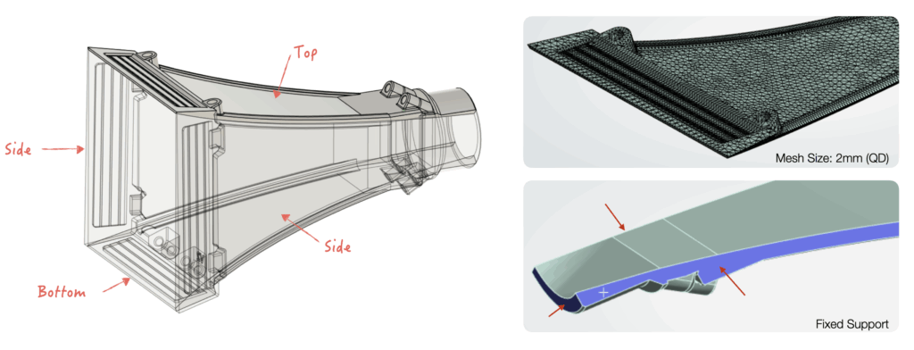
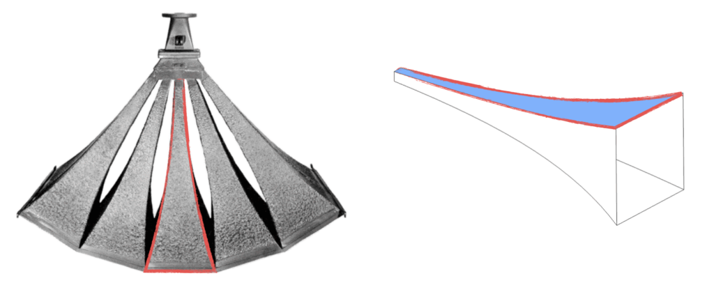
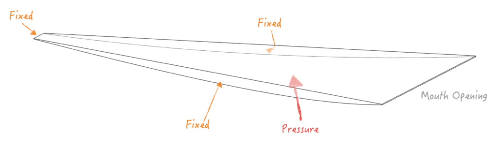
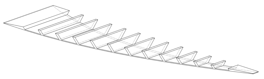
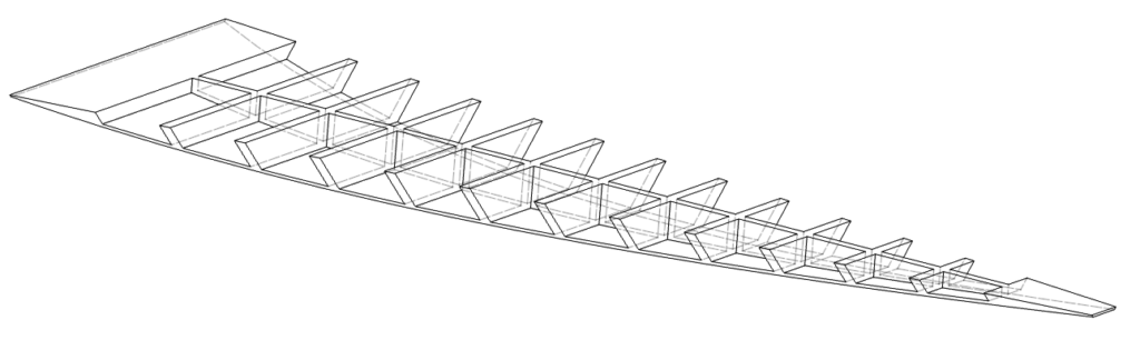
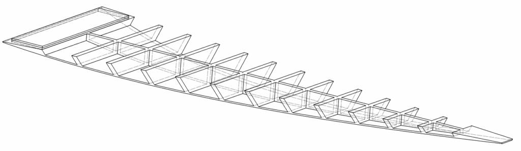
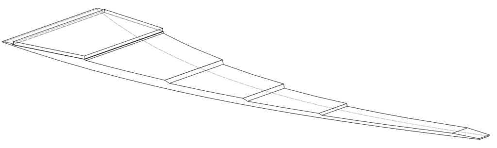
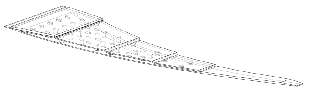
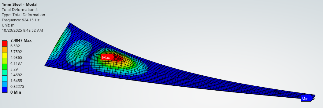
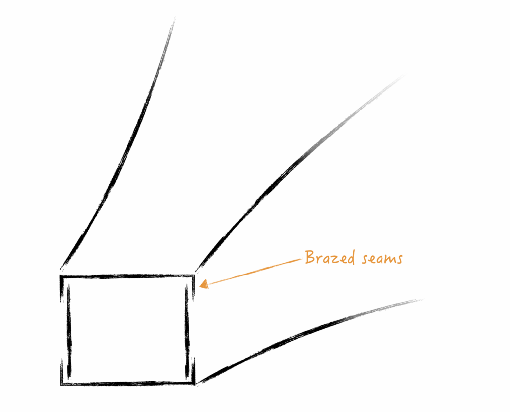
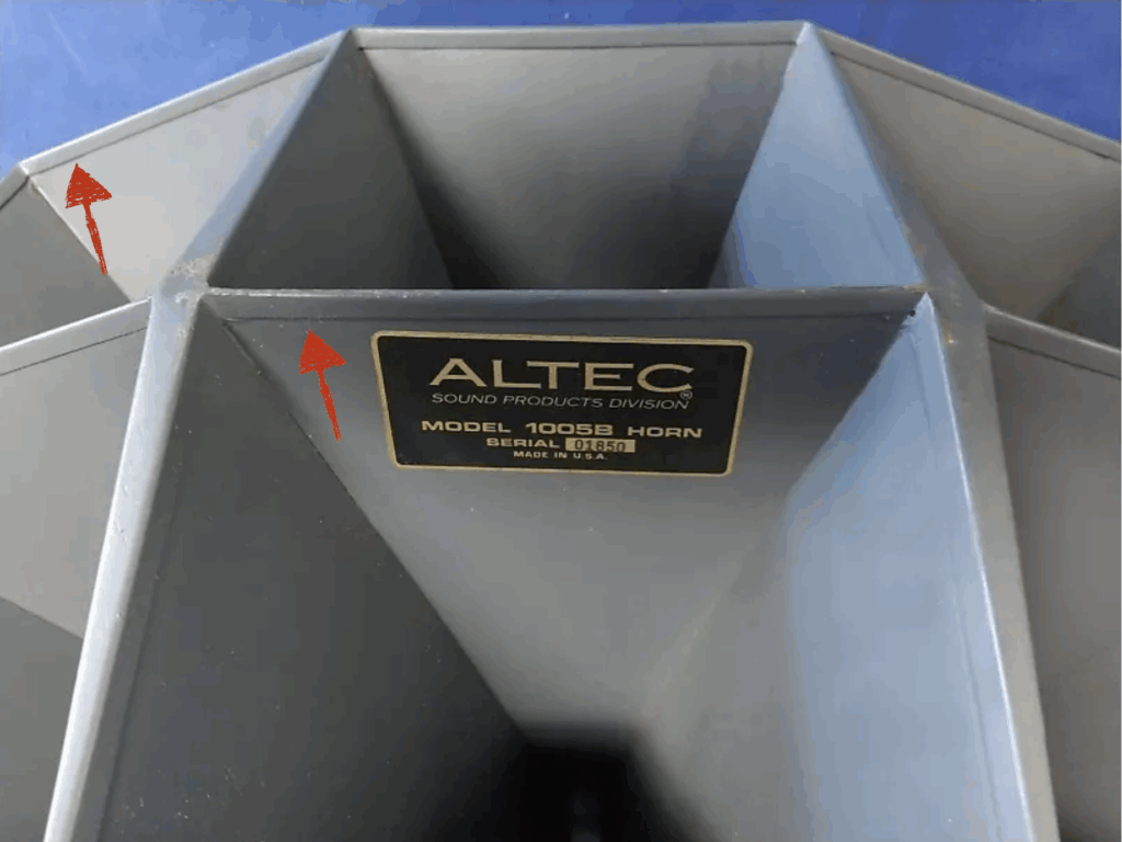
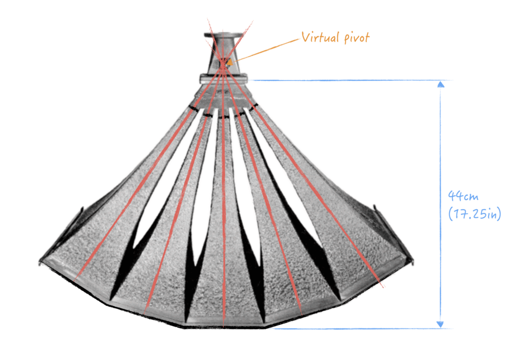
    I decided to rerun the modal simulation again with the actual horn geometry. I had to split up the horn into four triangular quadrants (Top, Side, Side, Bottom) as the mesh was too big otherwise.

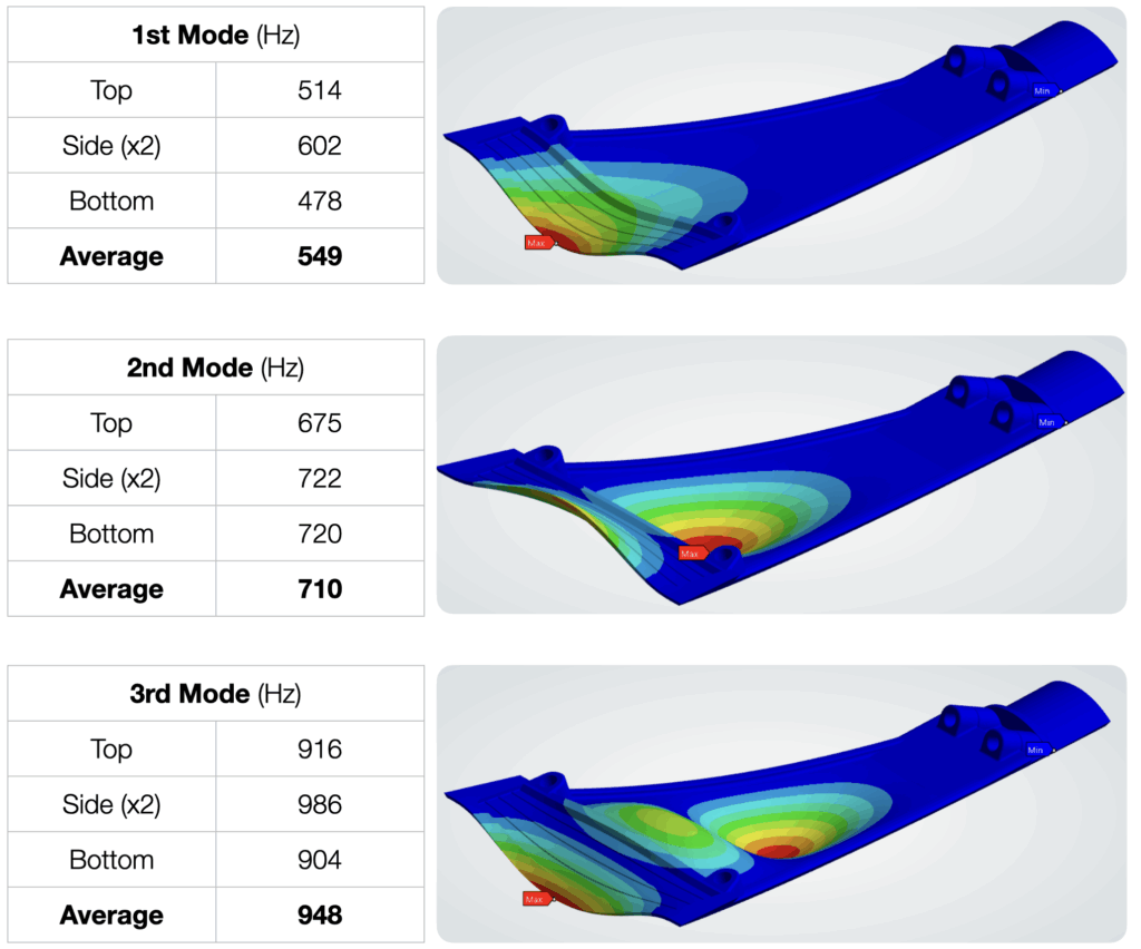
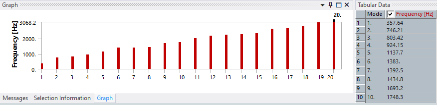
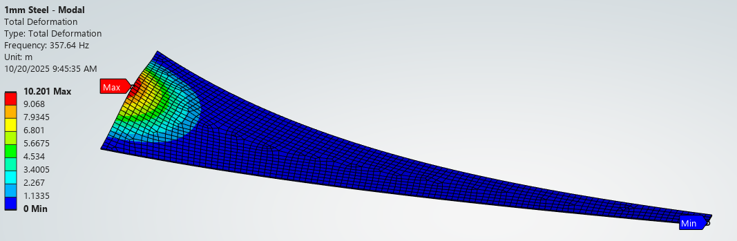
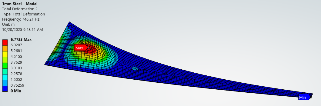
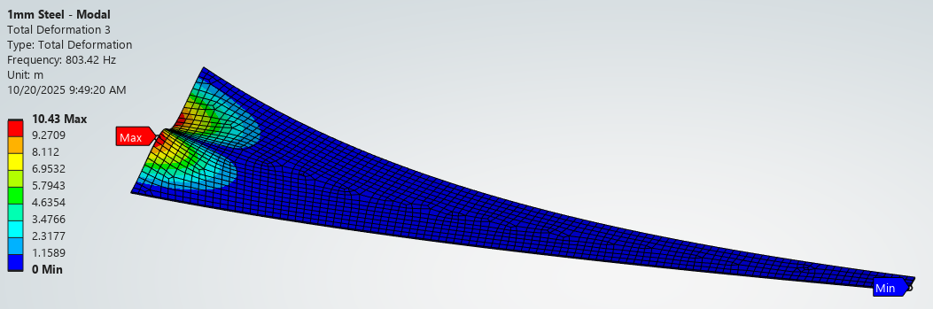
    For each quadrant, the splitting flanges and mouth flange were fixed to eliminate torsional and bending modes. Simulation results are shown below grouped by modes. Each quadrant showed slightly different resonant frequencies and a simple average was taken to arrive at a single value. This, surprisingly, actually got within 50Hz of the physical values! I would call this data “usable” for now and have some confidence simulation can be used in design.


    Conclusion:

    In this post, the first 3D-printed Mouth Section was built and tested. Damping material was added to various locations and the horn was measured and compared to baseline. Several mechanical resonance dips can be observed in the measurement data roughly corresponding the first three modes. The modal simulation was rerun with the actual physical horn modal in order to improve correlation. It was able to get much closer to predicting the problem frequencies.

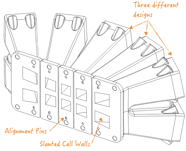
    The next section will focus on the design and testing of various Mouth Section configs to find one with the best damping performance. I now have the basic understanding of where the problems are, how to predict them, and how to treat them.

  • Altec 1005B: #4 Mouth Section – Design with FEA

    Study Method / Setup:

    We will examine the behavior of a single cell in the 1005B and, in fact, only one side wall of a single cell. The assumption is that all cells and all cell walls are identical.

    The image below shows a typical “wedge” for this study. Three ends are fixed as shown. A static deflection simulation will be performed by applying pressure onto the entire interior wall. A modal simulation will be performed with the same constraints minus pressure.

    Note: This assumes the Mouth Opening is unconstrained by adjacent cells and should represent the worst case free deflection.


    Assumptions:

    The following properties are assumed for the simulation. Only elastic properties will be used to due low deflection.

    MaterialProperties
    1005B CellMaterial: Steel
    Elastic Modulus: 210GPa
    Density: 8000 kg/m³
    3D Printed CellMaterial: PETG HF
    Elastic Modulus: 2GPa (100% infill)
    Density: 1400 kg/m³
    Aluminum StiffenerMaterial: AL6061
    Elastic Modulus: 70GPa
    Density: 2700 kg/m³
    Steel StiffenerMaterial: Steel
    Elastic Modulus: 210GPa
    Density: 8000 kg/m³

    The original 1005B is assumed to have cell wall thickness of 20ga (~1.0mm). This is the best guess I could find online.

    For configurations with stiffeners, the bond is assumed to be ideal line-to-line contact with no glue thickness.


    Design Configurations:

    Many brainstorming concepts are shown below, ranging from the simplest case to rather elaborate designs. Hollow internal features and various stiffener configurations were explored.

    Steel – Baseline
    20ga (1mm) Steel

    Steel – Thin
    26ga (0.5mm) Steel

    PETG – Solid
    3mm

    PETG – Ribs #1

    PETG – Ribs #2

    PETG – Ribs #2 + Stiffener

    PETG – Wedge

    PETG – Wedge Hollow

    PETG – Stepped + Stiffener

    PETG – Stepped Hollow +
    Stiffener

    PETG – Stepped Hollow +
    Stiffener 2


    Static Deflection Results:

    ANSYS was used to evaluate the design. The mesh was generated using the automatic tool (manual refinement was not done.) As visible below, the software defaulted to a mix of quad and triangular meshes.

    Pressure of 1Pa was applied to the internal surface (equivalent to 93dB SPL). This should represent a home listening level. As reference, the Altec 288-16K compression driver is capable of producing 110dB SPL @ 1W (or 6Pa @ 1W) and has a maximum input limit of 15W!

    The resultant deflection from the 1Pa pressure is minuscule and well within the linear region. As an example, the Steel – Baseline config shows a maximum deflection of 4.4×10⁻⁸m or 44 nanometer. We can expect the displacement to increase for higher operational pressure but it should still be within the linear region.

    Steel – Baseline
    20ga (1mm) Steel

    Steel – Thin
    26ga (0.5mm) Steel

    PETG – Solid
    3mm

    PETG – Ribs #1

    PETG – Ribs #2

    PETG – Ribs #2 + Stiffener

    PETG – Wedge

    PETG – Wedge Hollow

    PETG – Stepped + Stiffener

    PETG – Stepped Hollow +
    Stiffener

    PETG – Stepped Hollow +
    Stiffener 2

    The weakest point is at the mouth opening for most configs. This is expected due to the large span. PETG configs are much weaker than Steel but adding cross section helps greatly. PETG configs with metal stiffeners are able to further reduce maximum deflection by an order of magnitude.


    Modal Simulation Results:

    The modal simulation output and first four deflected shapes for the Steel – Baseline config is shown below. The first mode, lowest frequency, is located at the mouth and higher modes involve material farther away.

    Interestingly, the third mode is transverse across the mouth. I’m curious if this mode can actually be excited by an acoustic pressure wave since the air displacement volume cancels out. Many such transverse modes exist in the simulation.


    Conclusion:

    In summary, eleven different configurations were tested for both static and modal behavior. The configs started as constant wall thickness cases to establish baseline and iterated into more elaborate designs. Majority of the effort was made to minimized static deflection in the mouth region.

    Note: many material assumptions and mesh simplifications were made to simplify the simulation. The results should only be used for comparative study and have not been correlated to physical behavior.

    ConfigurationMax Deflection (10-8m)1st Mode2nd Mode3rd Mode4th Mode
    Steel – Baseline (1mm)4.47357746803924
    Steel – Thin (0.5mm)22.7219463509619
    PETG – Solid (3mm)22.9259496636718
    PETG – Ribs #15.82458100610971263
    PETG – Ribs #25.15501110511671697
    PETG – Ribs #2 + Stiffener0.57614135515231790
    PETG – Wedge Solid2.3374713341621 1964
    PETG – Wedge Hollow2.725977019471100
    PETG – Stepped + Stiffener0.291000187120872473
    PETG – Stepped Hollow + Stiffener0.49696121614481627
    PETG – Stepped Hollow + Stiffener 20.3976794115941762

    We are able to infer the following static deflection behavior:

    • For PETG only configs: adding material at the mouth is able reduce max deflection. Some configs are able to match max. deflection of the baseline.
    • For PETG + stiffener configs: max. deflection can be further decreased 10x of the baseline. Is this actually beneficial for acoustic performance though?
    • Deflection Zone: max. deflections typically occur at the mouth where the span is largest.

    We are able to infer the following modal behavior:

    • For thin wall and PETG only configs: low resonant frequencies are observed. Many have the 1st Mode below the 500Hz intended cutoff. Maybe this means they won’t be excited? But for many, the following three modes fall between 500 – 1000Hz and can definitely be excited. It will be important to find damping material that can be effective at these frequencies.
    • For thick wall and stiffener configs: First resonance is pushed much higher to the 500-1000Hz region and following modes are way above 1000Hz. This is beneficial as higher frequencies as easier to absorb with thinner damping material.
    • Modal Zone: All first four modes occur near the mouth.

    Next Steps:

    The above result confirms my initial suspicion that the mouth section can indeed be problematic from a rigidity and resonance perspective. There are several configs that look hopefully (especially the stiffener configs.) It is optimistic to see that adding local cross section in PETG is able to match the mouth stiffness of the baseline.

    The next step is to start building some of these configs.

  • Altec 1005B: #3 Detailed Design

    Original Manufacturing Method:

    The original multicellular horns were manufactured using sheet metal brazing. Individual cells were first assembled consisting of the four sides. Two of the sides have stamped flanges to allow the braze to fill. This is visible in the images below. The four sides were then placed into a fixture and carefully hand brazed by skilled technicians.

    Damping material was then applied over the majority of the cell. The ten cells (ie: for building a 1005B) were then fixtured into the correct position and brazed into the final assembly. I assume there is leeway to “massage” the length and shape of each cell to nicely fit each other. A sheet metal cap is then added to the mouth region which stiffens the edges, fills the in-between gaps, and provides a nice cosmetic finish.

    On the throat end, cell-to-cell regions were brazed to seal the gaps. A cap (appearing to be brass casting) is then brazed around the terminate to allow attachment of the throat adapter. The multicellular is now essentially complete. This is all very labor intensive work! It requires many tools to correctly manufacture and assemble the components. To achieve this quality is quite incredible and I wonder if it is still a feasible product today.

    Image Source: reverb.com

    Subcomponent Division:

    While it is possible to completely replicate the original method, it is the 21st century, and we now have access to more tools than ever. The goal of this project, as previously stated, is to explore 3D printing as the primary manufacturing process. It will allow prototyping and manufacturing of near-net-shape components requiring minimal labor.

    The first step is to decide how to split the 1005B into smaller chunks for manufacturing. The entire horn is much too big to fit onto a standard 3D printer. In this case, the size limit is a Bambu Lab X1C with a moderate print volume of 256 x 256 x 256 mm (~10.25 x 10.25 x 10.25 in).


    I decided to attempt splitting each cell into three pieces (mouth, mid, and throat section). The mouth and mid section should ideally be the same for all ten locations.

    The throat section should ideally be combined to capture the detailed geometry and thin walls where sound is split. The region is of particular interest because it handles the transition from plane wave to “spherical” wave. It will be interesting to optimize this transition and be able to do so without rebuilding the whole prototype.

    The throat adapter is for expanding the CD (compression driver) exit to the correct rectangular shape. Building this as a separate piece will allow experimenting with different expansion rates and also CD’s with different exit diameters.


    Assembly Method:

    The horn should be easy to assemble using reversible fasteners. The preference is to use machine screws with threaded inserts. This will allow the horn to be dis-assembled without accumulating wear on the plastic.

    Each section needs to have a tight fit to ensure acoustic performance. Gaskets will be used at joints to ensure seal.


    Design Overview:

    Below is the final iteration of the first-prototype design with all the details ironed out. The design mostly follows the intent set out above. Symmetry is used where possible. All sections are 3D printable without needing support material. The mouth sections are identical for ease of manufacturing.The mid sections are not identical because of a planar joint to the throat section. This requires three different designs to match the angles. This planar face is the downward face for 3D printing and provides adhesion for the overhang. Screw bosses/threaded inserts are used as fastening between sections. We will explore the design in more detail below.


    Mouth Section:

    The mouth section is the largest section of this design and takes almost the entire Z-limit of the 3D printer. It is meant to be printed mouth-opening down for stability and no support material is required for any overhangs.

    The mouth walls are wider at the bottom to take up gaps to adjacent cells. The geometry shown is specifically for the 1005B stacking pattern. The wedge will be much larger for the 1505B. The internal walls maintain the original square profile.

    Wall Thickness: Different thicknesses/infills are being considered with respect to acoustic performance vs. manufacturability. The cell wall near the mouth is exceptionally thin/long and therefore not rigid. Material has been added here to enlarge to contact area between cells to provide rigidity. Metal stiffener pockets are also added so aluminum/steel plates can be glued if needed. This is especially important for the outer edges of each cell (where there is no adjacent support).

    The plan is to experiment with different combinations of wall thickness/damping material/stiffener to achieve the best performance. Thicker walls will be stiffer but can increase print time (high infill). Stiffener and damping material can be added but can increase assembly labor.


    Mid Section:

    The mid section will perhaps be the most difficult section to print due to the significant overhang. The upper/lower cells of each 1005B “cell column” have been joined due to limited spacing and will improve component strength. Threaded inserts are to be heat-staked at the mouth joint side. The spacing here is quite tight and will need to be checked during assembly. The walls are purposefully designed very thick for acoustics and strength. Print time is significantly impacted due to smaller component size.

    Throat Section Interface: The decision to use a planar joint for this interface is a risk. The alignment and tolerances must be controlled carefully to prevent acoustic discontinuity at this junction. Ideally, the horn profile should be entirely continuous without any disruption that can cause reflections. The sealing gasket here represent a challenge as well and needs to follow the tapered geometry of the opening. Dowel pins have been added for alignment but success will ultimately depend on the print quality.


    Throat Section:

    The throat section faces the same manufacturing challenges as the mid section above. The component is to be printed “Face Gasket” face down and has significant overhang right from the start. First layer adhesion and cooling parameters will be critical to get the geometry right and prevent elephant-foot/other defects. This component is very rigid as it needs to reliability connect the horn section to the heavy compression driver.

    Acoustic Splitting Geometry: The current splitting design into the ten cells is questionable. The exponential expansion is continued as far as possible but eventual overlap and turns into undefined expansion. The interface opening is also not rectangular but a hourglass shape. The splitting “wedges” are minimized to ~1.5mm thick with a round. This seems like a good starting point given the modulus of the plastic. Going thinner may just result in a thin resonant wall that colors the sound. These design details can be experimented with later but is sufficient for initial testing. This component can be easily iterated on without impacting its neighbors.


    Throat Adapter:

    The throat adapter is a temporary design for now. The original Atlas design uses a 1.4″ exit compression driver (ie: Atlas 288) which transitions to a rectangular shape with an unknown expansion rate.

    I am using a 2″ exit compression driver for now. The surface area of the hour glass shape is almost the same the 2″ exit. Therefore, this throat adapter is provides only shape change but no expansion. The effect of this is to be seen and may result in weird resonances. This component will be iterated on as well for different compression drivers.


    Wall Thickness / Damping / Acoustic Performance:

    At this point, the biggest question is the acoustic performance of the 3D printed parts. There is an almost infinite combinations of wall thickness / infill / damping / stiffener to experiment with. Intuitive, the mouth section appears to be the most challenging as it interacts with the lowest frequencies and has the thinnest walls with largest span. Wall resonance here seems likely.

    The other sections are physically smaller, don’t have such space constraints, and can be easily made stiffer. They are, however, subject to higher pressure from the compression driver. This may become an issue at high levels but shouldn’t be for home use (maybe I need to clarify my design requirement). I’m also curious if the lower elastic modulus of plastic will regardlessly color the sound (compared to a metal surface).


    Next Steps:

    It is perhaps worth evaluating a smaller section of the horn instead of building the entire 1005B at once. The mouth section will be investigated first for wall resonances and design alternatives. It will be a good read on feasibility of 3D printed horns.

  • Altec 1005B: #2 Reverse Engineering

    Starting Point / Available Information:

    We will make the following assumptions: 
    - Cells follow pure exponential expansion to provide even loading and sound distribution. 
    - Cells are square and identical to each other and also identical between 1005B / 1505B. 
    
    This should appear obvious by examining the various resources online.

    The official dimensions from the Altec datasheet are shown below. We can deduce which dimension corresponds to which axis by comparing the differences between the 1005B and 1505B.

    1005B1505B
    30 x 17.25 x 13in
    76 x 44 x 33cm
    (W x H x D)
    30 x 16.75 x 18.5in
    78 x 78 x 47cm
    (W x H x D)
    2 x 5 cells3 x 5 cells
    40 x 100 deg60 x 105 deg
    Note the mistake for the metric 1505B height dimension. It should be 43cm instead of 78cm.

    The width is 30in corresponding to the common 5-cell direction of the horn. The depth is 13in / 18.5in corresponding to the 2-cell and 3-cell direction. The height is the 17.25in / 16.75in dimension which also includes the brazed on adapter plate.


    At The Mouth:

    Markus Klug (who builds beautiful handcrafted wooden replicas) shared the 1505B cell mouth dimension as ~16cm (~6.3in). From the datasheet above, we can also deduce each cell is ~6.5in in height.

    Original Source: Markus Klug

    We observe that Altec first assembles the cells into “columns” with the minimum gaps across the horizontal joint lines (red lines, below). Each column is then joined the adjacent columns. This creates a wedge shaped region (black lines, below) which is filled in. The size of the wedge is defined by the outer two contact points.

    Image Source: Audio-Database

    At The Throat:

    The cells are joined in a “pseudo-spherical” manner and brazed to get everything sealed up. The adapter plate is planar and seems to assume a planar wavefront from the compression driver.

    Image Source: eBay Item

    We can approximate the cell throat dimension by examining the throat adapter. The 1005B throat adapter is Altec PN 30210 which has external dimensions of “125 x 120 x 110mm (4.9 x 4.7 x 4.3in)” (according to various online sources.)

    Using a front-projection image, the throat opening width can be calculated to be around 80mm (3.15in). This gives roughly ~16mm for throat opening size of each cell (ignoring off-axis projection).


    Virtual Pivot:

    Using a topdown image (below) and drawing a centerline through each cell, a virtual pivot can be observed beyond the length of the horn. Note: the datasheet dimensions do not include the throat adapter.

    Image Source: Audio-Database

    In Summary:

    Cell Shapesquare, pure exponential
    Cell Mouth Opening~ 16cm (6.3in)
    Cell Throat Opening~ 1.6cm (0.63in)
    Cell Length~ 44cm (17.25in)

    1005B Skeleton Sketch:

    The info above is sufficient for creating a skeleton sketch of the horn in 3D. This represents the placement and stacking of each individual cells within the 1005B. After a lot of tweaking, the coverage angle is able to closely match the original datasheet. The cell-to-cell mouth spacing was slightly increased to allow thicker walls. This is important since the intentional is to design for 3D printing.


    Cell Design:

    The specific exponential flare rate can then be found using the above mouth, throat, and length dimensions.

    S = S0emx

    Then the side wall profile can be calculated, plotted in X/Y coordinates, and imported into CAD. Using a higher point density will improve curvature quality near the mouth.


    Initial Hornresp Simulation:

    The first sanity check is to simulate a simple exponential horn with Hornresp.

    Hornresp input for a single cell. Driver parameters and back chamber resonance are minimized.

    Three sets of S1/S2 surface area values (representing a single cell, 1005B, and 1505B) are plotted below for acoustic impedance and power.


    Single Cell Results:


    10x Cell Results:


    15x Cell Results:


    All above configurations have the same F12 cutoff frequency at 286.5Hz since they have the same flare rate. The advertised operational cutoff frequency of 500Hz is ~1.75x the F12 which respects the typical horn design rule-of-thumb.

    The response ripple is typical of a finite horn termination and is more severe on the single cell. By itself, the single cell is not recommended to be used down to 500Hz. However, this is where the multi-cell benefit comes in: The combined surface area of all the cells makes for a much smoother response . The response ripple decreases significantly and is more suitable down to 500Hz. “Strength in numbers” is applicable here.

    The results here make sense and aligns with the original Altec datasheet. I’m sure those fine Altec engineers knew exactly what they were doing. But it is amazing that they were able to get here with rudimental equipments over 75 years ago.

    Note: Many simplifications were made with this simulation. The driver surface area (Sd) was assumed to be equal to the horn throat area (S1) .This is not realistic but is simpler than creating throat transition geometries which will definitely affect the result. The acoustic power noticeably increases with the larger Sd. Driver parameters were also simplified to avoid high frequency roll off.


    Patent Excerpts:

    We can refer back to the original patent by E.C. Wente for more insight. The entire four page patent is worth a read and contains great details. An excerpt of the patent is included below:

    Note: The horn described by E.C. Wente converts a planar wavefront to spherical by having curved cell walls. This is not the case with the Altec design which does not really treat this issue at all. It will be interesting to see the performance difference between these two designs.


    Additional Reading:


    Acoustic Devices
    (US Patent#1992268) by E.C. Wente

    Quarter Wavelength Loudspeaker Design
    by Martin J. King

    Introduction to Horn Theory
    By Bjørn Kolbrek

  • Altec 1005B: #1 Introduction & Motivation. Why 3D Print?

    Inspiration:

    I have always admired the Altec “Voice of the Theater” since first becoming interested in horn speakers. The design is simple, practical, imposing, and almost intentionally brutalist. It clearly shows its intent: to deliver a wall of sound to your face.

    The image above shows the Altec A5 with two separate speaker unit. The top half is the high frequency unit (1005B multicellular horn) and the bottom half is the low frequency unit.

    Buying and owning one seemed highly impractical.
    Where would I even put something this big? Wait, how much does it weigh? 
    Hmm, maybe I can buy the top half and build a smaller bass horn? 
    I mean, the top half doesn’t look that complicated. Maybe, I can just build one?
    Ya! Let’s just build one!

    Rational reasoning falls apart when one tries looking for a deeper meaning in these projects. I guess this will still be a good engineering exercise to learn more about classic exponential expansion and get into the really nitty-gritty of horn building.


    Why Altec 1005B?

    The 1005B was chosen because it was the most “moderately” sized of the Altec Multi-cell catalog. The naming convention is as follows:

    300Hz Cut-Off:
    203B = 2 cells
    803B = 8 cells
    1003B = 10 cells

    500Hz Cut-Off:
    805B = 8 cells
    1005B = 10 cells
    1505B = 15 cells

    The 500Hz cut-off horns are actually smaller than the 300Hz series due to the shorter wavelength at cut-off. Examining the brochure above, all 500Hz single cells “appear” to be the same dimensions. This doesn’t appear to apply to the 300Hz series. Especially not for the 203B which is significantly larger than the other two models.

    One of my primary limitation is the size of my 3D printer which is the Bambu Lab X1C. Rough calculations show that a single 300Hz cell mouth won’t fit on the print bed. The 500Hz cell will fit but need to be divided length-wise to realize the full horn. Given that all 500Hz cells appear to the be same size, I was hopefully that I could adapt the design to the other configurations later if desired.


    Why 3D Print?

    I wanted to use 3D printing because I wanted a design that is easy to iterate and easy to build without metalworking tools. 3D printing also offers great flexibility in geometries / materials that are difficult to manufacture otherwise. The design could also be manufactured on-demand without significant investment in tooling and setup.

    The foreseeable challenge with 3D printing is matching the acoustic performance of the original metal horn. Plastic is inherently not as stiff and 3D printing often uses partial infill which may be more transmissive. Damping / resonance performance will be critical in the thin regions. Reliability is also a concern with exposure to sunlight / temperature in hot environments. Some plastics (PLA) may not be suitable for outdoor use.


    Goals:

    • Replicate the Altec 1005B Multicellular Horn
    • Match (or exceed) acoustic performance of original metal horn
    • Use 3D printing as primary manufacturing method
    • Easy to assembly without specialized tools, glue, or welding

    Existing Work / References:

    I cannot claim to be the first to attempt this. There is a great thread “The Construction of a Multicell Horn” on diyaudio.com with contributions from various member building similar designs with wood and 3D printing.

    I also cannot claim to be an expert in acoustic sciences as some of the math far exceed my level. I am currently studying “High Quality Horn Loudspeaker Systems” which has been an incredible reference for all things horn related.

    The original patent for the multicellular horn by E.C. Wente is also worth a read at “Acoustic Devices” (US Patent#1992268)