Starting Point / Available Information:
We will make the following assumptions:
- Cells follow pure exponential expansion to provide even loading and sound distribution.
- Cells are square and identical to each other and also identical between 1005B / 1505B.
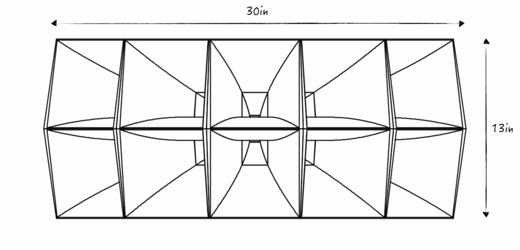
This should appear obvious by examining the various resources online.The official dimensions from the Altec datasheet are shown below. We can deduce which dimension corresponds to which axis by comparing the differences between the 1005B and 1505B.
| 1005B | 1505B |
|---|---|
| 30 x 17.25 x 13in 76 x 44 x 33cm (W x H x D) | 30 x 16.75 x 18.5in 78 x 78 x 47cm (W x H x D) |
| 2 x 5 cells | 3 x 5 cells |
| 40 x 100 deg | 60 x 105 deg |
The width is 30in corresponding to the common 5-cell direction of the horn. The depth is 13in / 18.5in corresponding to the 2-cell and 3-cell direction. The height is the 17.25in / 16.75in dimension which also includes the brazed on adapter plate.
At The Mouth:
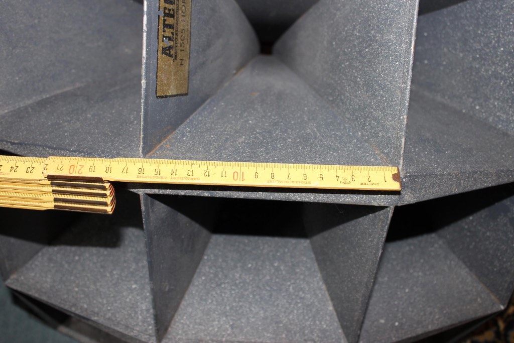
Markus Klug (who builds beautiful handcrafted wooden replicas) shared the 1505B cell mouth dimension as ~16cm (~6.3in). From the datasheet above, we can also deduce each cell is ~6.5in in height.
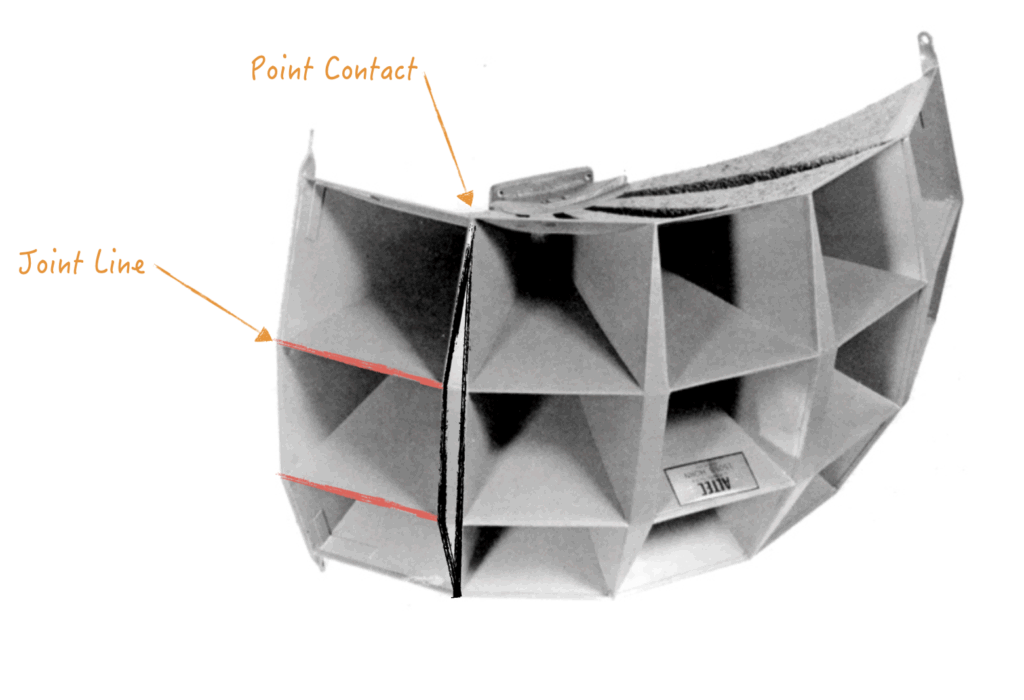
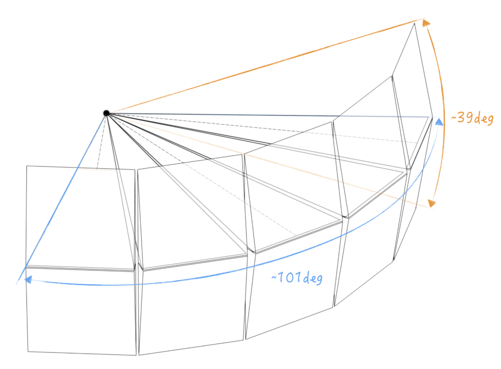
We observe that Altec first assembles the cells into “columns” with the minimum gaps across the horizontal joint lines (red lines, below). Each column is then joined the adjacent columns. This creates a wedge shaped region (black lines, below) which is filled in. The size of the wedge is defined by the outer two contact points.
At The Throat:
The cells are joined in a “pseudo-spherical” manner and brazed to get everything sealed up. The adapter plate is planar and seems to assume a planar wavefront from the compression driver.
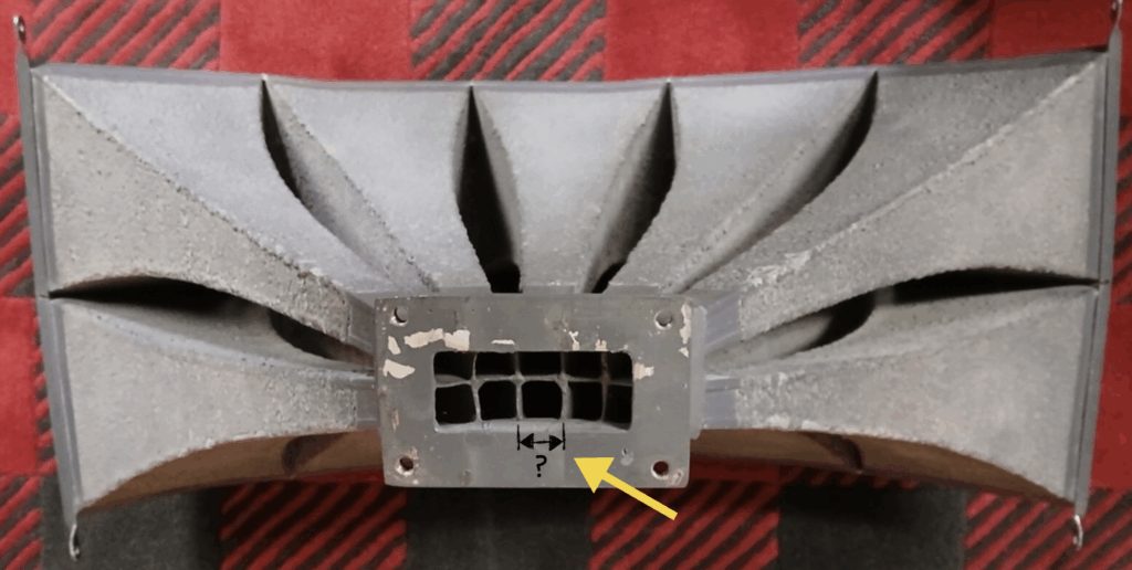
We can approximate the cell throat dimension by examining the throat adapter. The 1005B throat adapter is Altec PN 30210 which has external dimensions of “125 x 120 x 110mm (4.9 x 4.7 x 4.3in)” (according to various online sources.)
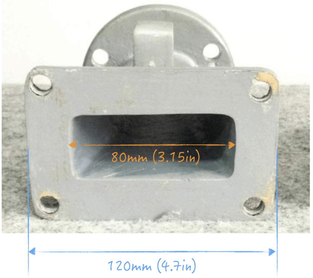
Using a front-projection image, the throat opening width can be calculated to be around 80mm (3.15in). This gives roughly ~16mm for throat opening size of each cell (ignoring off-axis projection).
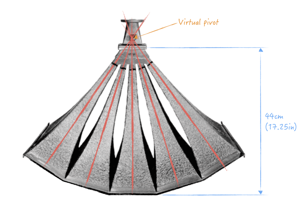
Virtual Pivot:
Using a topdown image (below) and drawing a centerline through each cell, a virtual pivot can be observed beyond the length of the horn. Note: the datasheet dimensions do not include the throat adapter.
In Summary:
| Cell Shape | square, pure exponential |
| Cell Mouth Opening | ~ 16cm (6.3in) |
| Cell Throat Opening | ~ 1.6cm (0.63in) |
| Cell Length | ~ 44cm (17.25in) |
1005B Skeleton Sketch:
The info above is sufficient for creating a skeleton sketch of the horn in 3D. This represents the placement and stacking of each individual cells within the 1005B. After a lot of tweaking, the coverage angle is able to closely match the original datasheet. The cell-to-cell mouth spacing was slightly increased to allow thicker walls. This is important since the intentional is to design for 3D printing.
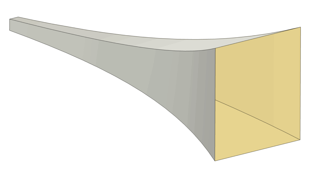
Cell Design:
The specific exponential flare rate can then be found using the above mouth, throat, and length dimensions.
S = S0emx
Then the side wall profile can be calculated, plotted in X/Y coordinates, and imported into CAD. Using a higher point density will improve curvature quality near the mouth.
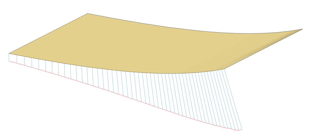
Initial Hornresp Simulation:
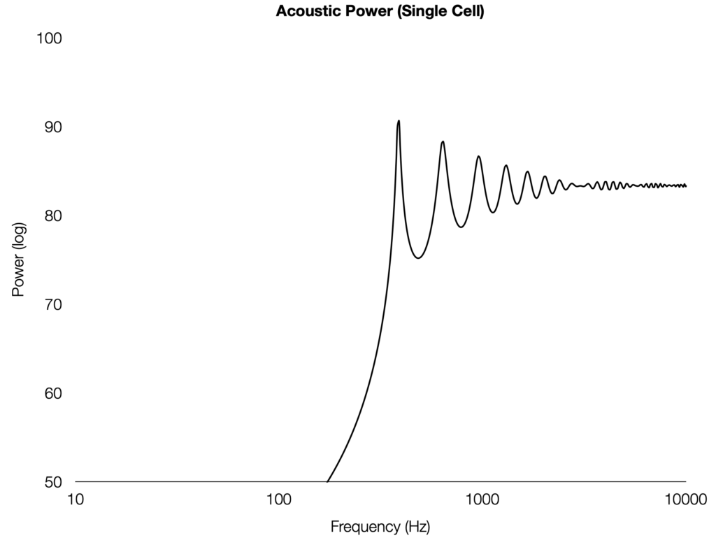
The first sanity check is to simulate a simple exponential horn with Hornresp.
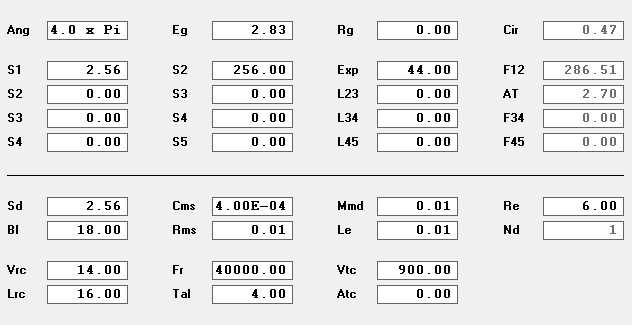
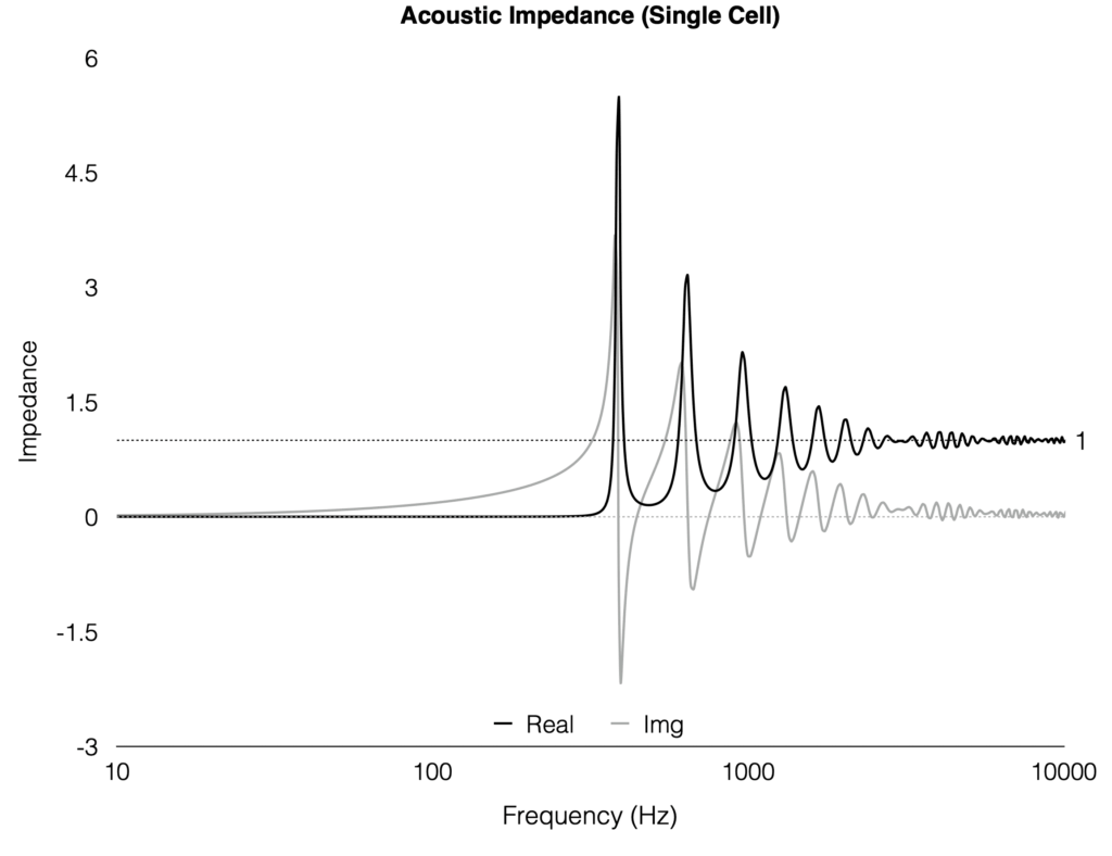
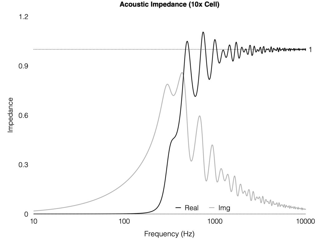
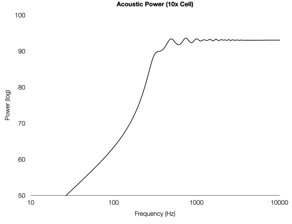
Three sets of S1/S2 surface area values (representing a single cell, 1005B, and 1505B) are plotted below for acoustic impedance and power.
Single Cell Results:
10x Cell Results:
15x Cell Results:
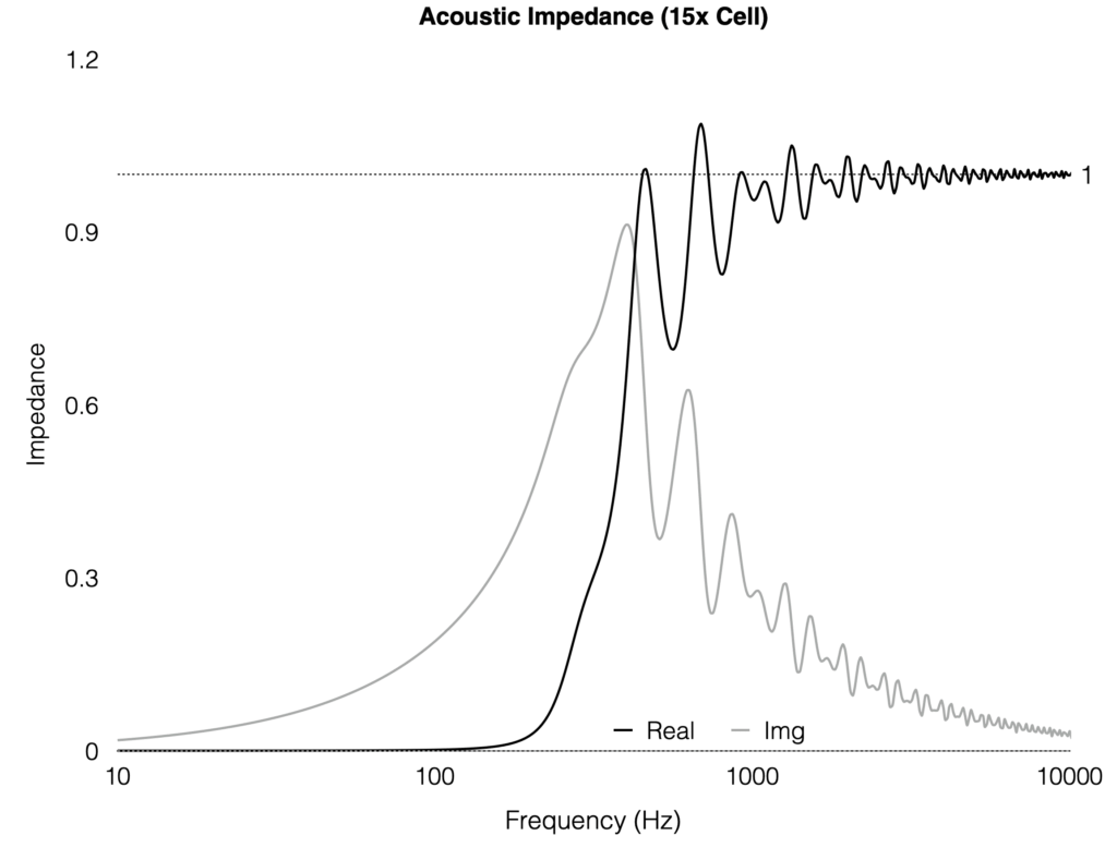
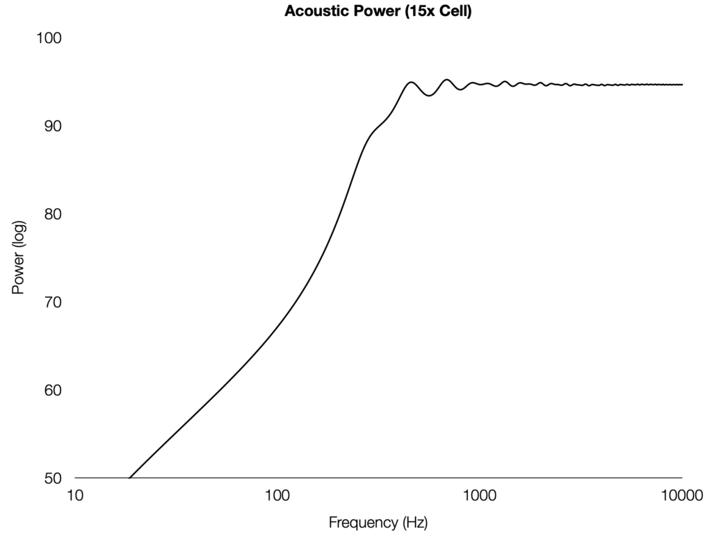
All above configurations have the same F12 cutoff frequency at 286.5Hz since they have the same flare rate. The advertised operational cutoff frequency of 500Hz is ~1.75x the F12 which respects the typical horn design rule-of-thumb.
The response ripple is typical of a finite horn termination and is more severe on the single cell. By itself, the single cell is not recommended to be used down to 500Hz. However, this is where the multi-cell benefit comes in: The combined surface area of all the cells makes for a much smoother response . The response ripple decreases significantly and is more suitable down to 500Hz. “Strength in numbers” is applicable here.
The results here make sense and aligns with the original Altec datasheet. I’m sure those fine Altec engineers knew exactly what they were doing. But it is amazing that they were able to get here with rudimental equipments over 75 years ago.
Note: Many simplifications were made with this simulation. The driver surface area (Sd) was assumed to be equal to the horn throat area (S1) .This is not realistic but is simpler than creating throat transition geometries which will definitely affect the result. The acoustic power noticeably increases with the larger Sd. Driver parameters were also simplified to avoid high frequency roll off.
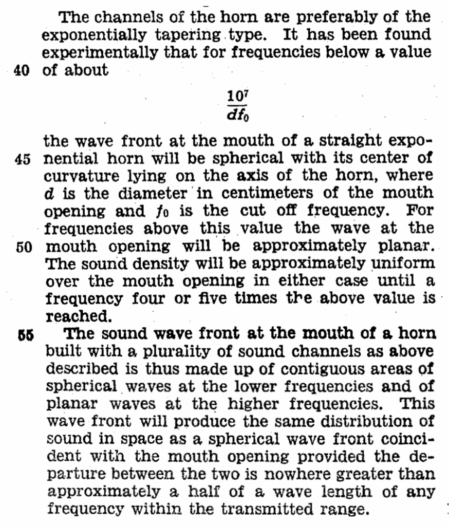
Patent Excerpts:
We can refer back to the original patent by E.C. Wente for more insight. The entire four page patent is worth a read and contains great details. An excerpt of the patent is included below:
Note: The horn described by E.C. Wente converts a planar wavefront to spherical by having curved cell walls. This is not the case with the Altec design which does not really treat this issue at all. It will be interesting to see the performance difference between these two designs.
Additional Reading:
Acoustic Devices
(US Patent#1992268) by E.C. Wente
Quarter Wavelength Loudspeaker Design
by Martin J. King
Introduction to Horn Theory
By Bjørn Kolbrek
Leave a Reply